Actuator and Joint Drive Research
Actuator Types
There are six general types of actuators commonly used in robotics projects:
- DC motor (Either brushed or brushless)
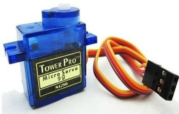
- Servo motor
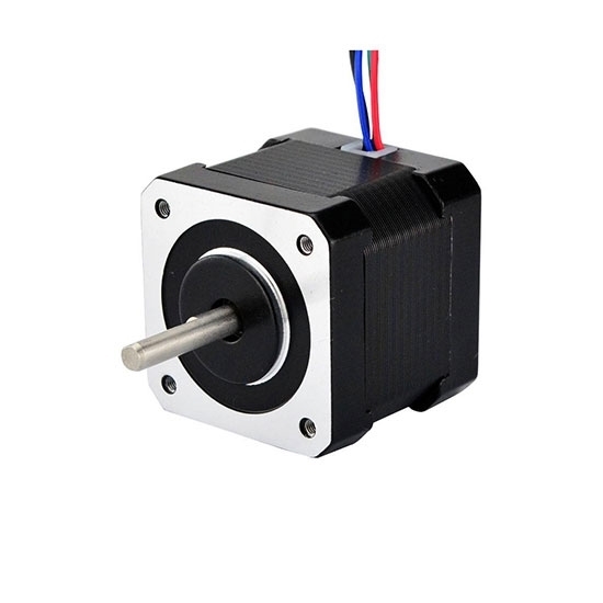
- Stepper motor
- Linear Actuator
- Solenoid
- Hydraulic Actuators
The type of actuator chosen for a specific application depends on a variety of factors, including precision, function, operating environments, etc. The following table outlines the advantages and disadvantages of these actuators.
| Motor Type | Example | Characteristics | Advantages | Disadvantages | Procurement Availability/Options |
|---|---|---|---|---|---|
| DC motor (brushed) |  |
|
|
| Robot shop, pretty much any motor vendor |
| DC motor (brushless) |
|
|
|
| The Robot Shop or other motor vendor |
| Servo motor |
|
|
|
| The Robot Shop or other motor vendor |
| Stepper motor |
|
|
|
| The Robot Shop or other motor vendor |
| Linear actuator |
|
|
|
| Progressive Automations |
| Solenoid |
|
 |
|
| Newark |
| Hydraulic Actuator |
|
|
|
| Motion Canada |


Actuator Examples and Specs
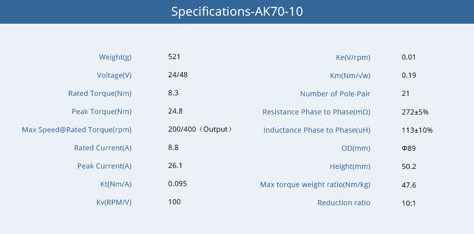
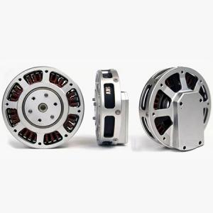
1. High torque robot dog joint actuators
- T-Motor AK70-10: https://store-en.tmotor.com/goods.php?id=1031

- MIT Cheetah Motor: https://www.robotdigg.com/product/1667/MIT-Robot-Dog-high-torque-Joint-Motor-or-DD-Motor

- Gyems RMD x8: http://www.gyems.cn/846351.html


2. Regular Brushless DC moto
3. Linear Actuators
Linear actuators are a form of motor used to transmit high force linear motion in small packages. If we want to use a linear actuator, it would best be suited to the translate the motion of axis 2 and axis 3.
4. Maxon Motors
Common Types of Joint Drives
Before reading this section, feel free to review the basics of power transmission to get a refresher on gear ratios and torque transmission ![]() .
.
Operation Fundamentals
Cycloid drives are a high stiffness and low backlash reducer. Typically, they consist of an input cam shaft, eccentrically mounted bearing, cycloid disc, outer ring pins and output roller and shaft. The cycloidal disk rotates around the outer pins via the eccentric cam, and achieves a gear ratio using the following formula: 
where:
- r: reduction rate
- P: number of ring gear pins
- L: number of lobes on the cycloid disk
As a quick example, a cycloid drive with 20 ring pins and 19 lobes on the cycloid disc will achieve a 19:1 reduction rate.

One drawback of cycloid drives is that when using a single cycloidal disc, the eccentric motion of the cam will generate vibrations that will propagate through the motor shaft. However, this is actually relatively easy to fix. Commercial cycloid drives use two cycloidal disks that are shifted by 180°. This counteracts the static imbalance, although generally very small vibrations may still prorogate through the shaft.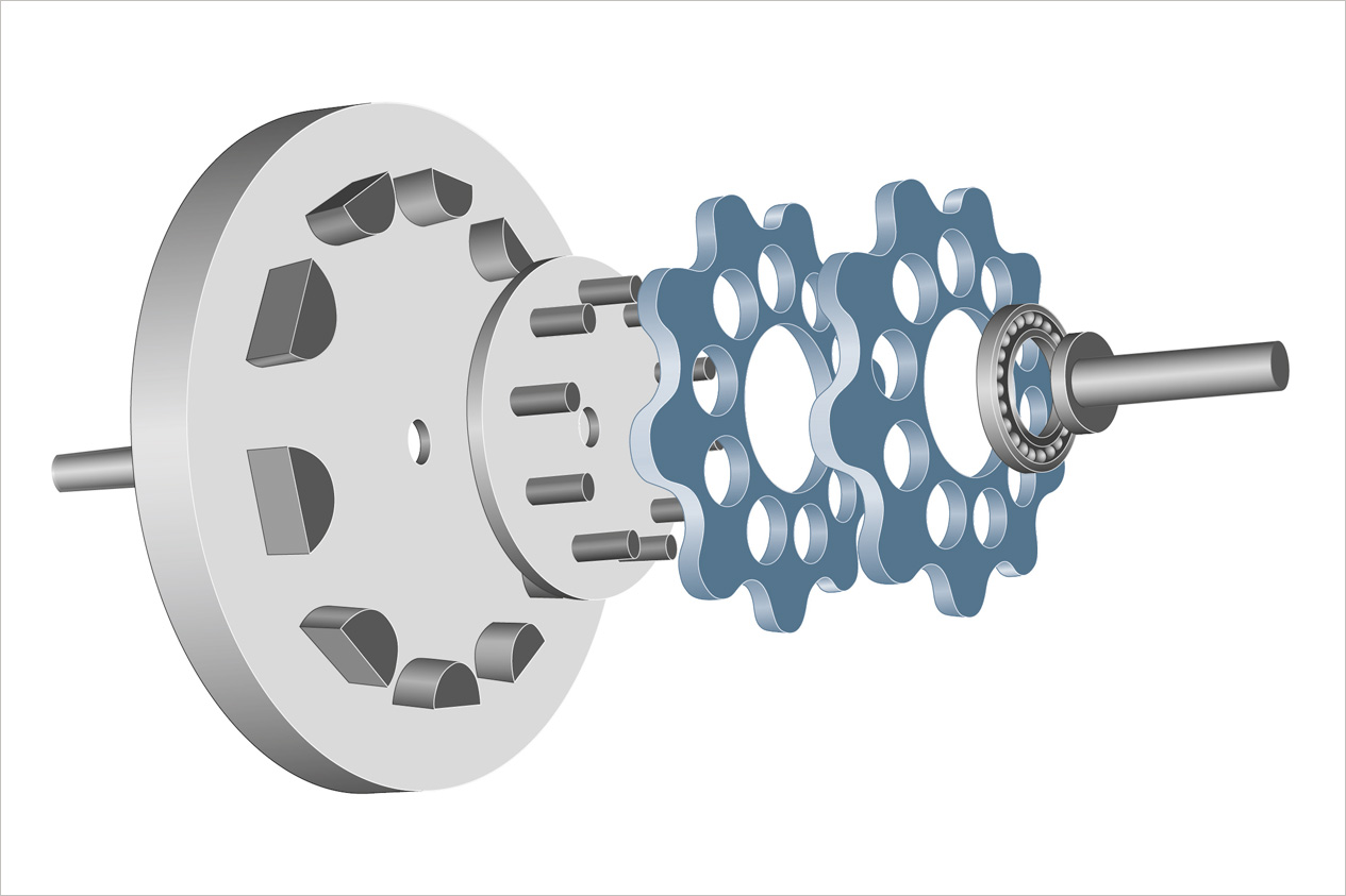
Backlash
In theory, a perfectly constructed cycloid drive will have zero backlash. When perfectly designed, the outer lobes of the cycloid disk will achieve perfect rolling motion with the outer ring pins, resulting in each lobe having one point of contact with any outer ring pin at all times (circled in green in the image below). The output rollers also achieve perfect rolling, so there are always points of contact between all moving components.

However, that is in theory. In reality, you need very precise machining between the cam, bearing, cycloid drive and outer ring pins in order to truly achieve zero backlash. If we design and construct our own cycloid drives, there will likely be some degree of backlash - especially when prototyping. The backlash of an OTS cycloid drive will likely be much lower, although whether or not it will truly have zero backlash can only be determined when testing in person.
Cycloid Drives vs Harmonic Drives
Cycloid drives often draw comparisons to harmonic drives due to their similar elliptical motion. This paper does a great job to outline an compare some of the key differences in performance between the two types of gears. According to this document, cycloid drives have superior profile/size, inertia and efficiency while harmonic drives have less backlash and torque ripple. However, there's one key thing that I think needs to be considered when reading this paper's claim that cycloid drives hold considerably higher backlash. This paper specifically compared the performance of cycloid and harmonic drives for anthropomorphic robot applications, meaning they compared the performance of small profile drives with very high gear ratios. Furthermore, they compared OTS harmonic drives with cycloid drives that they custom designed and machined to try and match the gear ratio and outer profile of the OTS strain wave gears. To illuminate why this should be considered, lets take a look at the highest backlash cycloid drive cited in the paper.

The custom cycloid drive designed to match the outer profile of the harmonic drive CSF-5 had a max gear ratio of 70 and a cited backlash of 1.4°. Heres a drawing of the CSF-5 that I found online. It has outer dimensions that show a square profile 22mm by 22mm.

If you design a cycloid drive with a gear ratio of 70, that means you have to cram 70 cycloid lobes in this thing, and need to make components just as small. The cited backlash probably has to due with the mating of some of the parts, as once again cycloidal drives need to achieve perfect rolling to have zero backlash and this thing would require some really small components.
My guess would be that larger cycloidal drives with smaller gear rations probably have a much lower degree of backlash and would be easier to produce, as the feature size of components becomes a lot larger and easier to work with. IDK tho, just something to consider ![]() .
.
OTS Options
There are some OTS options for cycloidal reducers from various vendors, but its hard to get prices until we can actually spec out some of our motor shaft sizes.
- Onvio Dojen Line (prob highest standard, some lower profile options available) https://onviollc.com/Products#cycloidal
- DieQua https://diequa.com/products/cycloidal-reducers/
- Sumitomo https://us.sumitomodrive.com/en/cyclo-gear-drives
- Nabtesco: https://www.nabtescomotioncontrol.com/en/
Buying these OTS may not be the most viable option. Although no prices are available after stalking ebay it looks like buying these without any form of sponsorship is gonna cost at least $500 USD. Also, there are made with really robust materials to offer high gearing ratios, so a lot of these brands (apart from the Dojen line) use really bulky and heavy housing. Weight is definitely a consideration for our arm, so having something bulky and expensive may not be ideal when we can somewhat realistically make these ourselves as well.
Custom Manufacturability
One reason I really like cycloid drives is that they they seem super easy to design in house. In fact, with the exception of maybe belt drives, they seem to be the simplest form of transmission that we can construct ourselves as the individual parts of the cycloid reducer are simple, albeit a bit tight on tolerances. There are tons of resources that simply the construction of these drives, with even solidworks blog even posting a document discussion how to build these drives (with equations provided for the cycloid disk and pins)! There are a lot of resources on youtube documenting the steps to create drives as well.
These drives are hard to get perfect, but we can easily prototype and iterate using 3D printed parts before machining the final reducer design out of aluminum or whatever rigid material deemed necessary. Some other teams have built these drives and it looked like they've used aluminum, lexan and other common materials for construction. However, it will probably take a lot of iteration to get these custom designs perfect and to be realistic we should aim for low (but not zero) backlash.
Here are the cycloidal gearboxes designed by Monash, and by Michigan


Recommended Joint Location
If we decide to use these types of reducers, I would recommend using them to turn the base of the arm and position the "forearm" style of linkage and not anywhere near the wrist and claw. The wrist and claw doesn't need to worry about backlash as much as the larger parts of the arm, as zero backlash wrist is a bit unnecessary - the wrist is small enough to where some backlash won't hugely affect it's precision, and cycloid drives are a bit too bulky to reliable fit in a small space if custom machined. However, they could be great to adjust the position of the base of the arm and forearm, providing low backlash and a sturdy drive to reduce torque and speed ![]() .
.
Extra Resources on Cycloid Drives
Operation Fundamentals
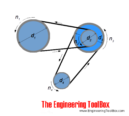
Belt drives use pulleys to transmit torque and power. Generally speaking, you have your input wheel (small diameter) that is connected to an output wheel (large diameter). The ratio of the belt drive works pretty much exactly as described in the Power Transmissions Basics guide, with the larger wheel having speed reduced and torque increased directly proportional to the difference in diameters of the two wheel sizes. Also, the movement of the two pulleys are related via the belt drive rather than direct mechanical mating. There are a couple different types of belt profiles used in power transmission, however robotics typically uses synchronous belt drives with integrated tooth profiles due to their higher level of precision.
Figuring out the power transmission of a belt drive is a little bit more complicated, as you need to calculate the teeth in mesh for the belt as well as application factor. We can research this more in depth if we want to use belt drives.
Backlash
I'm having trouble figuring out citable values for the amount of backlash experienced by belt drives. I think this is due to the fact that finding a citable value for this is pretty complex. Obviously, the teeth that mesh into the pulleys have some degree of clearance that can allow for backlash as you move the timing belt. However, timing belts are under constant tension if designed correctly, and are typically made from either urethane or neoprene which are high friction materials that are less likely to experience slipping on the pulley. As such, backlash doesn't work the same as with a regular gear, as the teeth themselves are under constant forces at all times. However, some searching online shoes that trapezoidal (trapezoidal just refers to the shape of the tooth profile) timing belt drives are known for having low or insignificant backlash when tensioned correctly. Timing belts are commonly used on high precision 3-axis robots like 3D printers, so hopefully that gives some context as to the backlash seen in the belt. I think general consensus is that there may be lower backlash with a belt drive than gearing if tensioned correctly, although this opinion comes from scanning through forum posts rather than academic research (as I couldn't find too much).

Belt Tensioning
As you probably noticed, I said that backlash is low when the belt drive is correctly tensioned. Properly tensioning your belt opens up a whole new can of worms if you want to do it correctly. Most belt drives you purchase will come with a recommended tension to meet in order to have the belt to operated as intended. Typically, when installing belt drives it will fit onto the pulley with some very minor slack, then the tensioning method will pull the belt into it's rated tension. There are a few ways to achieve this.
- Linear belt tensioner: Linear belt tensioners are used to manipulate the centerline distance of the pulleys to achieve greater tension. These kinds of systems would be easy to design and implement on our arm, and probably a bit too expensive to buy a compatible OTS solution. Typically OTS variants have very specific geometry, so implementing this becomes more of a constraint - designing our own would be cheaper and simpler.

- Spring Loaded Belt Tensioner: Spring loaded tensions are used to manipulate the pathing of the timing belt to increase tension. These guys seem to be the more commonly used belt tensioning method in high speed applications, but would be difficult to implement in our design as deflection calculations would be required to optimize the position of the spring loaded tensioner. Its super hard to custom design these, but you can buy them on grainger or amazon for $40 bucks on the cheap end, and $100+ on high end. Buying these OTS options also proposes design constrains for the linkages due to their mounting geometry.

- Belt Clamp: You can also use a belt clamp to tension the belt. This is what we use on science mechanism, but this system doesn't work if the belt will do complete revolutions around the pulley.
Belt tension isn't something that gets held for ever, and reduces over time. If we use belt drives, we will probably constantly have to tighten the drive to minimze our backlash.
Belts as a Backlash Solution
Saw something really cool, so gonna add this section in here.
If you have a gearbox suffering from high backlash, you can use an additional timing belt stage to reduce the backlash it experiences. This could be super useful for our purposes, as we can use less precise gearbox with higher backlash as a base, then add a timing belt for a higher reduction ratio and reduced backlash!
OTS Options
Neoprene and urethane timing belts and pulleys are readily available on McMaster Carr. If we plan to use timing belts, we should definitely chose urethane variants over neoprene due to their higher precision.
Custom Manufacturability
Think its pretty obvious that we aren't gonna custom machine a timing belt and pulley. That being said, the housing for these systems on the links will definitely be a custom solution, as there is no one size fits all for timing belts - it's very design specific. I think now would also be a good time to discuss some drawbacks of timing belts. First (and most obviously), they take up a large profile as the belts themselves must be free to move over the linkage, and easily accessible for maintenance. Belt drives will stretch and lose their tension over time, so they need to be replace more often than gears (but are much cheaper to replace). Our linkage design would be a lot more constrained if we want to accommodate belt drives, as we need space to freely fit the whole belt drive and tensioning hardware. Also, its difficult to reach higher reductions on belt drives as it's unrealistic to use a super large diameter gear and timing belt. To achieve higher reductions, multi stage timing belts are generally used however this also takes up a space consideration.
Recommended Joint Location
If we want to use belt drives, we should probably look to doing so on the wrist/forearm side instead of arm base and shoulder. The arm base and shoulder should have minimal backlash and high torque which is harder to achieve with a belt drive (rather than planetary, cycloid or strain wave). Belt drives are commonly used in the forearm/wrist operations of industrial robots as they allow you to cluster the motors all at the top end of the forearm for better center of mass optimization. They are also useful in this location, as lower backlash and torque requirements are present as these joints. That being said, I think belt drives might be a bit of a pain to set up and deal with compared to regular drives due to their large profile and constant maintenance.
Extra Resources
Operation Fundamentals
Spur/helical/bevel gears are probably the most common types of transmission. They transmit varying torque and power pretty much exactly as explained in 9 - Power Transmission, so check out that page if you want to figure out how the gears work.
Spur gears and helical gears are very common in their operations, and both types of gear typically feature two parallel gears that mate together. The only difference between the two are that spur gears feature straight cut teeth, where as helical gears have angular cut teeth. Helical gears have a higher contact ratio on the teething than spur gears, allowing for higher torque and speed transmission for the same size at the cost of a higher axial gear load. Helical gears are used more commonly in robotics due to their higher torque transmission, but to use them over spur gears you do need to account for the additional axial thrust loads. Also, helical gears can be used to transmit rotation and torque in perpendicular shafts, but I think there are better options to achieve this if necessary, as the mating design can get messy.
Stock spur/helical gears are cut to operate at standard distances, defined by:
Standard Centerline Distance = (Pinion Pitch Diameter + Gear Pitch Diameter) /2
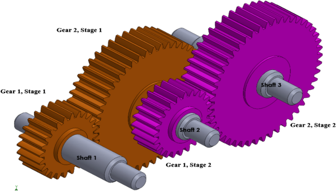
Single stage helical and spur gears typically have pretty low reduction ratios, with the max reduction for spur gears reaching ~ 1:6 and max reduction for helical gears reaching ~ 1:10. However, the main benefit of helical and spur gears is that they allow for very high transmission ratio through multiple reduction stages. You can stack up multiple stages of transmission in a low profile of gears to achieve high transmission ratios, like shown below. This is likely overkill for our robot arm, but if we really need high transmission we can look into spur or helical gears as an option. When using these transmissions, we also need to consider that the backlash will stack up between mated teeth, so backlash could be increased.
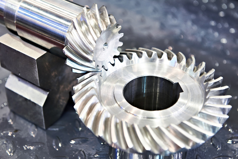
Bevel gears feature an angled tooth profile to allow the transmission of power to perpendicular shafts. Tooth profiles for bevel gears come in multiple forms, such as straight and spiral which offer the same benefits and drawbacks as discussed for spur vs. helical gears. Single stage bevel gears have an approximate standard max ratio of 5:1.

However, bevel gears can improved by shifting to a hypoid gear design. In bevel gears, the two gear axis intersect at a center point. In a hypoid gear, the axis of the two gears are shifted by an offset, which allows for MUCH higher power transmission (up to 200:1)! However, hypoid gears are difficult to mesh properly, and require more maintenance (constant lubing) as the meshed teeth are under higher pressure.

Backlash
All gear types in this section require backlash to operate. Backlash is required to allow for the smooth operation of mating gears, and reduces friction by preventing grinding. If you run these gears at 0 backlash, they can seize and fail. I've been able to find some standard backlash gears for spur gears, but not for helical gears. Some sources say that helical gear backlash is lower than spur, but I haven't been able to find too many published values on this notion. These values relate directly to the standard centerline distance formula discussed above. Didn't find too many published values on backlash in bevel gears, as it's mostly dependent on centerline distance for mated gears, reduction ratios and suppliers. There are formulas posted for all types of gears, but as far as empirical values go I would assume backlash between spur and bevel gears is relatively close. General consensus is that these types of gears produce the highest amount of backlash as the types of transmission discussed on this page. Keep in mind tho, that lower pitches will experience lower backlash as physically there is less space for the teeth to wiggle. 
To reduce backlash in spur and helical gears, the main two options are to change centerline distance in gears or adjust tooth thickness. For our design purposes, only changing centerline distance would really be a feasible option. As an alternative, there are vendors who offer split spur (but not helical, from what I've seen) gears that use split tooth profile and springs to reduce experienced backlash. These use a spring to push half of the split gears teeth into the open space to prevent backlash when gearing stops moving, but still allow for minimal backlash to occur due to the flexibility of the spring. These gears are pretty expensive (72 dollars each from some estimates) so alternate non backlash options can be explored.

OTS Options
Spur, standard beve; and helical gears are readily available from multiple gear manufacturers, with KHK being a really easy to access vendor. Hypoid gear models are more difficult to find and procure, from what I've seen they come from mainly international suppliers.
Custom Manufacturability
We could probably machine spur and straight bevel gears ourselves if we wanted to, however purchasing gears is a MUCH better alternative IMO. Custom machining gears is super unnecessary. Spur and helical gears require pretty precise tooth profiles to be accurate, so it's better to leave those designs for an expert. Helical and spiral bevel gears would probably be difficult to manufacture. Also, these types of gears aren't too expensive, probably ~ $35-75 each (approximations from KHK website).
Recommended Joint Location
Due to their inherent backlash, I don't think we should really consider any of these the main joints. However, they may be useful on the wrist or end effector where backlash considerations are less significant, as they can be used to increase reduction ratios through their multiple stage transmission and are relatively simple to install.
Extra Resources
https://khkgears.net/new/gear_knowledge/gear_technical_reference/gear_backlash.html
https://www.motioncontroltips.com/hypoid-gearboxes-what-are-they-and-where-are-they-used/
Operation Fundamentals
Worm gears offer high ratio transmission to perpendicular axis in a compact profile. A small worm gear is butted against a worm wheel, and the transmission ratio is calculated by dividing the number of teeth in the worm wheel by the number of threads in the worm gear. However, the worm gear typically consists of a single thread, meaning the transmission of the worm gear overall is effectively "Teeth on Worm Wheel" : 1. This value can be changed depending on the number of starts on the worm wheel, however for our applications multi start worm gears are probably unnecessary, as we care about high torque instead of high transmission speed. Worm gears are pretty much always non-backdriveable, with the worm wheel being unable to transmit rotation to the worm gear due to high friction. However, if we do need backdriveability for a worm gear application, some multistart worm drives can* (can being a maybe, in theory it should be easy but backdriveability may still be difficult in practice due to high friction) offer a somewhat backdriveable option at the cost of ratio.
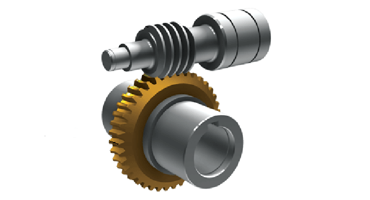

Just as a note, while the worm wheel looks like a standard spur gear, it's actually not the same. Worm wheels have a curved inner profile to allow for better meshing with the worm gear, so make sure you order worm wheels to go with the worm gear!

Backlash
Worm gears also feature some degree of backlash between the worm gear and wheel, depending on the set up and gear meshing of the teeth. There are formulas used to describe this backlash, and the total amount can vary from situation from situation. The same methods for reducing worm gear backlash discussed with bevel gears apply, where you can reduce the centerline distances of the gears to reduce backlash at the risk of increasing wear, friction and standard gear operations. However, backlash can be reduced by implementing duplex worm gears, which have a differential thickness on the tooth profile of the worm gear. You shift the worm gear across it's axis of rotation to adjust backlash by changing tooth thickness until a desired value is reached.

Custom Manufacturability
Very unnecssary, as worm gear options are very readily available from vendors. I guess we could cut our own worm gears if we really wanted to, but it definitely seems pointless.
OTS Options
Standard and duplex worm gears are available on KHK to various sizes. Standard worms are also available super cheap on mcmaster.
Recommended Joint Location
Worm gears would definitely be great to use on the wrist, forearm or end effector as they can provide super high transmission ratios in single stages in a compact profile. However, if we want to main precision i wouldn't use them on any of the larger joints unless duplex worms were used, as they do have some backlash. Worm drives are also really great in any location we deem non-backdriveable joints to be necessary
Extra Resources
https://en.wikipedia.org/wiki/Duplex_worm
Operation Fundamentals
Planetary gears are a three part gearing system consisting of a sun gear, planet gears/carrier and outer ring gear. When operating, either the ring gear, planet gear carrier or sun gear is held fixed and one of the other two components serve as the driven and drive gear. When used as a motor reducer, typically the sun serves as the drive, the carrier serves as the driven output, and the ring gear remains stationary.

Calculating gear ratios for planet gear are pretty simple. Once you have established which components are fixed, drive and driven you can figure out ratio by dividing # driven teeth / # drive teeth. To determine number of teeth you have, you can count can teeth on the sun and output rings, then # of planetary teeth in mesh are equal to # sun teeth + # ring teeth.
Planetary gears are a lot better than standard spur gears, as they can reach ratios up to 10:1 in a single transmission stage. This is a much higher ratio than single stage spur gear options. I should mention this now, but limits on transmission ratios for standard and planetary gearing, or any gearing for that matter have to do with realistic sizing usage. Most applications of gearing operate under a space restriction, and transmission ratios typically are proportional to the difference in diameter of the two gears. Tooth pitch for driven and driving gears has to be the same to allow the teeth to mesh properly, so as you continue to scale things up ratios, gear operations become impossible without lowering pitch (which increases tooth spacing so high that the gears will be useless).
Backlash
Planetary gears can also suffer from backlash, with sources quoting 90-180 arcmin (1.5-3 degreees of play). That seems like a shit ton tho, and IDK if its that bad in real life. I think we would need to contact suppliers when determinig the true backlash of these gears (if we plan to buy it). I also don't know if that quoted backlash value is listed for input or output, as that would vary the resultant backlash. I've seen some high precision planetary gears that offer much lower backlash, so honestly I'm not 100% how to quanitfy expected backlash. Sources claim that backlash in planetary gears is lower than other gear types, but with no values provided. This is probably because for similar external gearing profiles, planetary gears can maintain the lowest tooth pitch due to their 3 component build, which helps reduce experienced backlash
Custom Manufacturability
If we want to use planet gears, some form of custom solution will likely be necessary. We would probably need wire edm to manufacture precise gears, and can probably test meshing and models with a 3d printer. Custom planetary gears would probably be limited to using standard spur tooth profiles, which is probably ok for our purposes. There are some good tutorials online on how to set up custom planetary gears.
OTS Options
There are some suppliers for planetary gearing sets, but typically we would need to integrate some sort of custom planet carrier to really use a planetary gearbox in our arm. As such, going custom for some of the parts would be a much better idea IMO.
Joint Locations
Planetary gears would be useful in joints where high reduction stages are required. While they do have backlash, there are some techniques to mitigate that (like the video in the belt drive section which uses a second stage to reduce backlash and increase reduction ratio). Planetary gears can offer the highest single stage reduction out of all other gear types in a small profile and are super compatible with second stage reductions, as you can use coaxial shafts to easily set up a second stage. They might be pretty easy to use on the elbow ![]()
Common Extra Resources