Revision 2 - F2020 - Cindy Li
- Former user (Deleted)
- Former user (Deleted)
Power Distribution Board
The Power Distribution Board takes as input 18V - 25.2V power from a 6s1p battery pack and supplies 24V power to the ethernet switch, 17V power to the Nvidia Jetson board, and 5V power to custom PCBs onboard the Mars rover robot.
DC power conversion is carried out through a buck-boost converter for 24V and buck converters for 17V and 5V. Battery reverse polarity protection is achieved through an ideal diode controller and external N-channel MOSFET. Each load is controlled by a high-side smart switch with open-load detection and current limiting capabilities.
The PDB also serves to control the LED Matrix board and interface with four URM04 ultrasonic sensors placed at the four corners of the rover to detect close-range obstacles.
Block Diagram

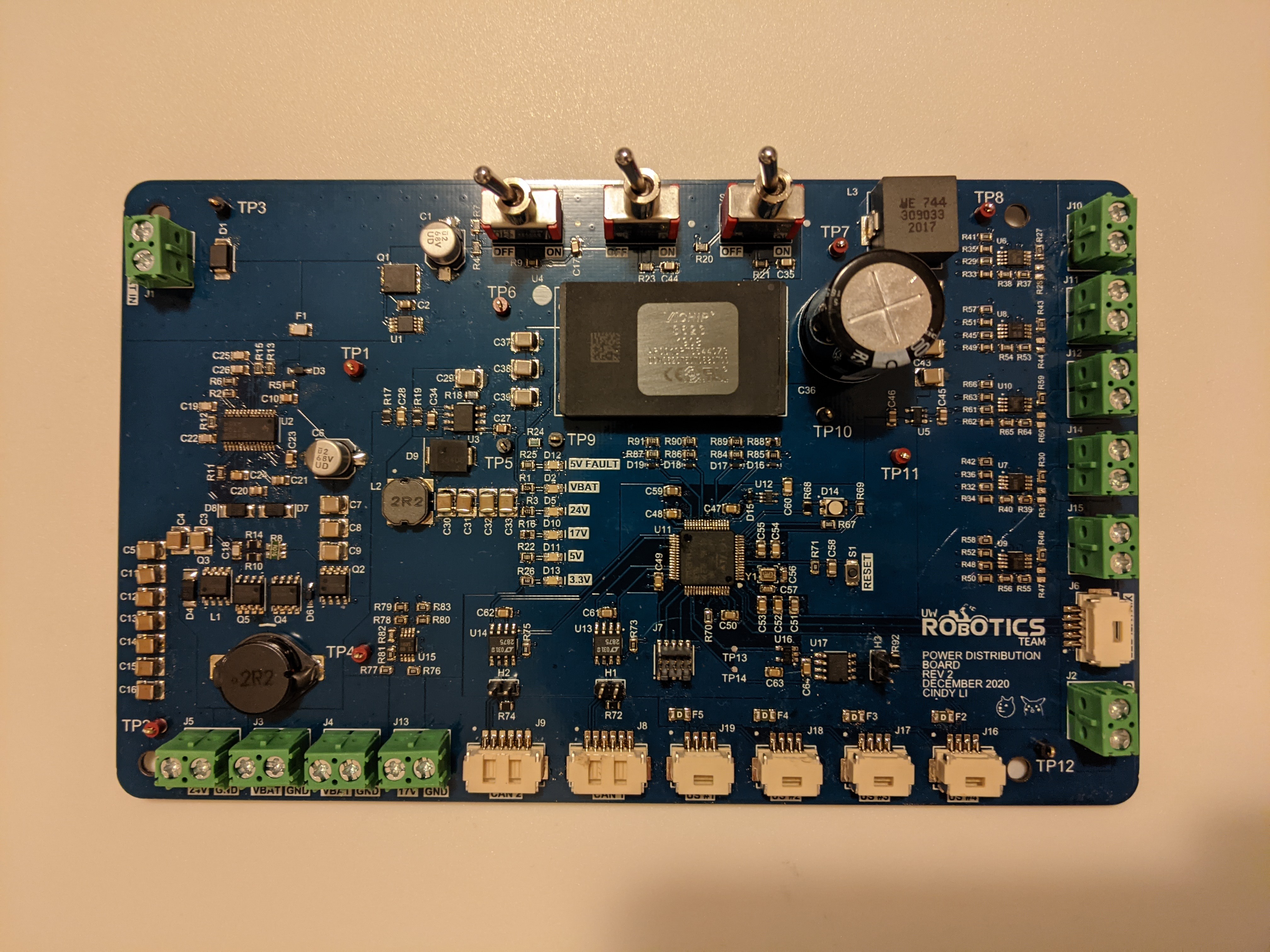
Assembled PCB
Reverse Polarity Protection
In the case that the battery terminals are accidently plugged in the wrong way, reverse polarity protection (RPP) helps to protect downstream circuitry from being damaged by the negative polarity that results. A very simple way of designing for RPP is to place a Schottky diode between the input power rail and the rest of the circuit. In the case of reverse voltage, the diode will block current flow and effectively act as an open circuit.

This method isn't the most efficient since a small amount of power is wasted through the diode's forward voltage.
On PDB Rev1, RPP is implemented by a P-channel MOSFET circuit:

In the case of reverse polarity, the Gate to Source voltage (Vgs) goes low and turns off the MOSFET, effectively disconnecting the input power supply from the rest of the circuit.
PDB Rev2 employs an ideal diode controller for RPP. An ideal diode acts like a real diode by conducting current when it is forward biased and acting as an open circuit when it is reverse biased. However, ideal diodes have virtually no forward voltage drop, making them very efficient.

The ideal diode controller IC controls an external N-channel MOSFET to connect or disconnect the input power supply from the rest of the board. The advantage of N-channel MOSFETs over their P-channel counterpart is that they have lower Rdson (drain to source on resistance), which is the resistance between the drain and source when the MOSFET is conducting.
Components
- Ideal Diode Controller
- MPN: LM74610QDGKRQ1
- Documentation
- Digi-Key link
Further Reading
24V Buck-Boost Converter
The PDB includes a 24V buck-boost circuit to supply regulated 24V power to the ethernet switch. A buck-boost converter is a type of switch-mode power supply (SMPS) which delivers an output voltage that is either higher or lower than the input voltage. See this page for the theory behind how buck, boost, and buck-boost converters work.
Components
- Buck-Boost Converter IC
- MPN: LM5175QPWPRQ1
- Datasheet
- Digi-Key link
Buck-Boost Testing
The PDB buck-boost output was tested with an electronic load at input voltages of 18V, 20V, 22V, 24V, and 26V:


Testing data shows that at the lower (18V - 20V) and upper (26V) ends of the input voltage range, the buck-boost circuit is capable of delivering a steady 24V for up to 3A current draw. However, when the input voltage is close to the output voltage (22V - 24V), the buck-boost output becomes unstable at much lower current draws than the targeted 3A. These results signify that the buck-boost output is unusable as it is incapable of delivering up to the 3A it was designed to.
Next Steps
- Replace the LM5175 IC with the LM5176 IC (same package, has optimized performance from the transition region from buck to boost) and retest the buck-boost
Full Testing Data:
17V and 5V Buck Converters
The PDB uses VBAT - 17V and VBAT - 5V buck converters to supply 17V to the Nvidia Jetson and 5V to all downstream PCBs. A buck converter is a common type of switch-mode power supply (SMPS) which delivers an output voltage that is lower than the input voltage. See this page for the theory behind how buck, boost, and buck-boost converters work.
Components
- 17V Buck Converter
- MPN: LMR14050SDDAR
- Documentation
- Digi-Key link
- 5V Buck Converter (Vicor DCDC Converter)
- MPN: DCM3623T50T0680
- Datasheet
The 17V and 5V outputs have been validated up to 4A and 16A respectively.
Testing Data
Rail Monitoring
The VBAT, 24V, 17V, and 5V power rails are monitored by the MCU through voltage divider analog sense lines. Each voltage divider scales down the rail voltage range to between 0-3V, which can be measured by the MCU's internal ADCs. A 3.3V Zener diode is added to each analog sense line to protect the MCU pins from overvoltage on the power rails.

Load Monitoring
The PDB includes high side smart switches to monitor its 5V and 17V loads, allowing loads to be turned on/off dynamically as well as overcurrent protection and open-load detection. Smart-switch current limits are programmed to 5A. In the case of an open-load or overcurrent event, a fault signal can be configured to be set to alert the MCU.
Components
- High-Side Smart Switch IC
- MPN: TPS1H200AQDGNRQ1
- Documentation
- Digi-Key link
Microcontroller
The PDB features an STM32F446RET6 microcontroller (MCU), with the following responsibilities:
- Monitor rail and load voltages and report faults
- Read ultrasonic sensor data
- Control the LED matrix board over 3 PWM channels
- Communicate with the rest of the rover system over CAN
Components
- MCU
- MPN: STM32F446RET6
- Documentation
- Digi-Key link
Ultrasonic Sensor Interfacing
The PDB interfaces with four URM04 ultrasonic sensors over a single RS-485 bus. RS-485 is a differential pair protocol. A MAX485 transceiver is incorporated to convert from RS-485 to serial UART.
Components
- RS-485 Transceiver
- MPN: MAX485CSA
- Datasheet
- Digi-Key link
CAN
The PDB is connected to the rover's two CAN buses for communication.
Components
- CAN Transceiver
- MPN: LTC2875
- Datasheet
- Digi-Key link
Project Documents
Designers
- Cindy Li - Schematic Capture and PCB Design - cindyli-13
Built With
- Altium Designer - The PCB design software used
Errata
- Introduce enable signals to load switches
- Add line driver / receiver control signal to MAX485 transceiver
- Fix test point silkscreen labels
- Fix 24V buck-boost output
- Add USB for UART printf and MCU powering without power supply
- Add current monitoring
- Make sure diodes are assembled in the right direction