Rev 1 - S2020 - Cindy Li
- Former user (Deleted)
- Former user (Deleted)
Localization Board
Localization Rev 1 is an R&D project with the goal of replacing our COTS IMU + GPS module with a custom PCB. The board houses a 9-DOF IMU and a GPS receiver module, interfacing with an STM32 microcontroller. The ultimate purpose is to enable robot localization through UWRT custom hardware.
Block Diagram
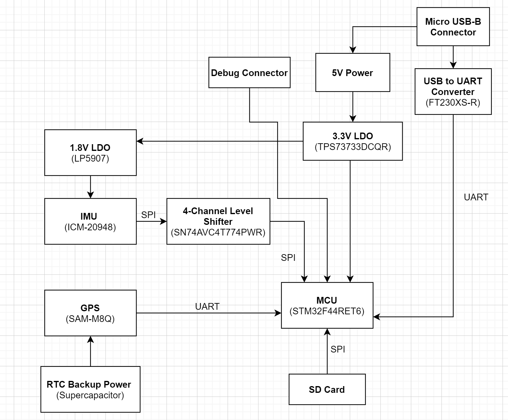
Assembled PCB

Sensors
The IMU-GPS pair is commonly used to determine robot position using a technique called sensor fusion. Sensor fusion takes measurement data from multiple sensors and "fuses" them to produce an optimal estimate of the robot's state. A commonly used sensor fusion algorithm is the Kalman filter (learn more here!).
IMU
- ICM-20948 - 9DOF IMU with Digital Motion Processor
- Interface: I2C or SPI
Inertial measurement units (IMU) are sensors that measure angular velocity and linear acceleration through a combination of gyroscopes, accelerometers, and sometimes magnetometers. These are used to determine an object's position and orientation in some reference frame. A 9-DOF (degree-of-freedom) IMU means that it consists of a gyroscope, accelerometer, and a magnetometer to give 9 separate measurements:
- Angular velocities (x,y,z)
- Linear accelerations (x,y,z)
- Magnetic field strength and directions (x,y,z)
GPS
- SAM-M8Q - u-Blox GNSS antenna module
- Interface: UART
A GPS receiver obtains GNSS satellite data to determine its geographical location on the Earth. The received data packets are timestamped data that includes the latitude, longitude, altitude, and various other information.
Level-Shifting
The IMU operates at 1.8V logic while the microcontroller operates at 3.3V logic. To allow communication between the two components, two 4-channel, bidirectional level shifters are used to translate between 1.8V and 3.3V logic levels.

USB Interface
The localization Rev 1 PCB includes a micro B USB connector and an FTDI circuit to convert differential USB to serial UART for the onboard microcontroller.
- FTDI IC: FT230X-R

Power Delivery
The PCB can be powered by a 5V power supply (screw terminal connection) or through USB (at 5V). An onboard LDO steps the 5V rail down to 3.3V to power the MCU. Another LDO further steps down the 3.3V rail to 1.8V to power the IMU.

ORing Power Supply
Since the PCB can be powered through either a screw terminal power supply connection or through USB, an ORing configuration is implemented using two Schottky diodes. If one power supply fails and is shorted, the Schottky diode isolates the short from the other working power supply.

Real-Time Clock Backup Power
The GPS module has a real-time clock (RTC) which can be powered by an auxiliary power source if the main power supply is disconnected. This auxiliary source could be a coin battery, but a supercapacitor was chosen instead because why not ![]() .
.

RTC Further Reading
SD Card
The PCB includes an SD card slot for purposes of storing GPS data.
Project Documents
Designers
- Cindy Li - Schematic Capture and PCB Design - cindyli13
- Alaina Hansen - Schematic Capture - alainahansen
Built With
- Altium Designer - The PCB design software used
Errata
- Tent vias
- Replace IMU with one that is easier to solder
- Replace GPS with one that is easier to solder