3D Printing - FDM
- Former user (Deleted)
- Lesley Lang
Table of Contents
Fused Deposition Modelling (FDM)
Fused Deposition Modelling is one of the most popular 3D printing processes, largely due to its low cost and easy accessibility to the public. Large databases of printable CAD models have grown over the years, thus enabling even those with minimal experience to explore FDM printing.
FDM printing is done by extruding heated material through a nozzle onto a bed which holds the final product. Material is extruded in layers and builds upwards. In order to support the printing material while it is still hot and easily deformed, support material is printed simultaneously to provide the part some structural stability while it prints. This support material can be broken off easily once cooled, or the part can be placed in a solution that dissolves only the support material. Typically, nozzle movement can be grouped into two groups: cartesian and delta. Cartesian printers use rails in the X, Y, and Z directions to allow the nozzle to move to specified coordinates, while delta printers use three longer arms that independently move the nozzle . The print bed can either be heated on non-heated, depending on the type of material used. Heating is usually required when materials are at risk of warping. Print spaces can either be enclosed, or open air, usually depending on the material used for printing. High material melting points require enclosed spaces otherwise there is a large risk of warping. Warping can occur when the correct temperatures aren't maintained throughout the print, leading to the material cooling unevenly and causing shrinkage where it cools [1].
Factors Affecting Print Quality:
Layer Height and Nozzle Diameter
Layer height, also called resolution or layer thickness, is the thickness of each printed layer, and is usually specified by the user. Increasing layer height reduces precision and makes it more difficult to print small features, however it reduces the overall print time. Nozzle diameter refers to the size of the extrusion hole that the material comes out of. It is important to make sure the right layer height is set based on the nozzle size, otherwise printing issues will arise. Layer heights should be set to 25-75% of the nozzle's diameter [4].
Layer Adhesion
Layer adhesion is critical for the quality of a print. Ensuring that each extruded layer properly attaches to the previous one is important otherwise delamination can occur. Delamination is when layers don't properly adhere, resulting in cracks and poor print quality. This can be avoided by lowering the speed of the nozzle which gives extruded material more time to stick to the underlying layer. Adjusting the extrusion temperature and cooling conditions to ensure the material is hot enough when it comes in contact with the model and that the whole model is cooled evenly [5].
Printing Alignment
The way a part is aligned on the printing bed can greatly affect the functionality, quality, and cost of a print. It can help reduce the amount of material used during a print, and increase the accuracy of complex features. Printed parts are weakest when stress is applied normally to their layers, so ensuring that the part is oriented so that its layers do not interfere with its functionality. Slicing software will usually auto align parts on the print bed to minimize material usage, however it may be beneficial to consider other orientations to ensure all the features of the part are printed properly.
Bridging
Bridging occurs when extruded material joins two areas of support across an area with no support. When making a hollow part, joining the roof of it from each side to close the part would be an example of bridging. If the length between the two supports is too large, sagging can occur and result in a poorly printed part. Sagging due to bridging can be resolved by either reducing the bridging distance, changing the part alignment, or printing with removable support material [10]. This can also be prevented my modifying nozzle parameters such as speed and extrusion rate.
Holes
Holes are best printed when facing upwards. Vertical holes (holes with their center axis parallel to the bed) are usually printed with lower accuracy due to nozzle's downwards pressure and gravity, and this results in smaller diameters and deformed circles (no uniform diameter). This effect is more prominent with smaller holes, so depending on the application, vertical holes might be acceptable to print. When designing parts with holes, aligning them so that they face upwards would be the best way to maintain accuracy [7].
Overhangs
Overhangs are angled features that only have partial support from underlying layers. Similar to bridging issues, material ca344pxn start to sag due to lack of support from underlying layers. Issues with adhesion can also arise when there is not enough surface area for the newly printed layer to attach to. Finally, having extreme overhangs can lead to their corners being much thinner than the rest of the part. This can lead to uneven cooling and warping. In FDM printing, around 45 degrees is acceptable for an overhang that is printed without support. If the overhang moves beyond this range, adding support material or modifying the part's alignment on the print bed can ensure good print quality [7].
Tolerances and Small Features
Based on the specifications of each printer, general tolerance guidelines are given and should be properly considered before designing parts to be printed. On average FDM parts have a dimensional tolerance of +/- 0.5% [[dimensional accuracy]]. Small features should be at least 0.8mm thick otherwise there is a risk of it not printing at all, or the part breaking off very easily if printed [[considerations]]. Thin walls should be filleted at their point of contact with other features otherwise they are more likely to break off [7].
Surface Finish and Post Processing
FDM printed parts can undergo many different post-print processes to improve the finish of the final product. When planning the production of a part, post-processing is faster than re-designing or adding in complex features [10].
- Sanding
- Polishing
- Gap Filling and Coating
- Priming and Painting
- Vapor Polishing (ABS and Acetone)
- Dipping
- Further reading on post processing FDM prints [10]
Materials
FDM Printers primarily print with thermoplastic polymers. These materials are soft enough to be extruded through a nozzle at high enough temperatures and solidify into a final-use product once printed and cooled. They have decent mechanical properties that are well suited for simple part, prototypes or models [11].
Some popular materials use in FDM printing are:
- Acrylonitrile Butadiene Styrene (ABS)
- Can be printed at higher temperatures
- High impact resistance
- Polylactic Acid (PLA)
- Biodegradable
- Widely available and easy to print with
- Polycarbonate (PC)
- High mechanical strength
- Brittle
- Nylon
- High impact resistance and strength
- Filament is very susceptible to damage from moisture
- Thermoplastic Polyurethane (TPU)
- Very flexible, however difficult to print with
- Polyethylene Terephthalate (PET and PETG)
- Not widely used in printers, so hardware should be checked to see if it is compatible with this material.
- Food safe
- Chemically resistant
- Acrylonitrile Butadiene Styrene (ABS)
| Typical FDM Material extrusion process [2] |
|---|
|

| Example of a Warped FDM Printed Part [3] |
|---|
|

| Example of a Bridging Failure in a Part [6] |
|---|
|

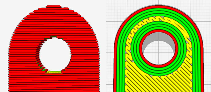
| Left: Hole's axis parallel to build sheet Right: Hole's axis is perpendicular to build sheet (best way to orient) [8] |
|---|
|
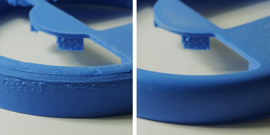
| FDM part out of the printer (left) vs post-processing (sanding) (right) [9] |
|---|
|