Hole and Shaft Standard Fits
- Former user (Deleted)
- Lesley Lang
- Former user (Deleted)
Table of Contents
What are Hole and Shaft Standard Fits?
Since tolerances between mating holes and shafts are considered so frequently, standard fits were developed [1].
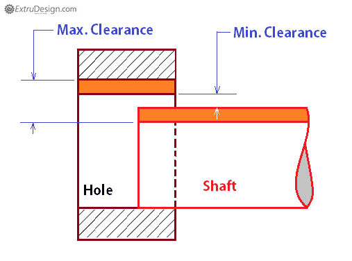
Clearance Fit
In clearance fits, the maximum allowable shaft diameter by its tolerance is always smaller than the minimum hole diameter allowable by its tolerance [1]. This makes for easy assembly and room for sliding and rotating [2]. There are several types of clearance fits; notable ones, sorted from most loose to most tight, include:
| Example of Clearance Fit [3] |
|
Loose Running Fit
Loose running fits have the largest clearance. They are usually used when accuracy is not a priority, and when corrosion, contamination (such as dust), or deformations (thermal or mechanical) may be a problem. This type of fit can be found in applications such as pivots and latches [4].
Free Running Fit
Free running fits are also used when accuracy is not a priority, and there is no need for precise guidance of shafts [2]. They are often used in environments with great temperature variations, high running speeds, and/or high bearing pressure (such as when lubrication is used between the shaft and bearing) [4].
Close Running Fit
Close running fits are used when accurate location and minimal play is desired [2], and there are moderate running speeds and bearing pressure. This type of fit can be found in applications such as machine tools, sliding rods, and machine tool spindles [4].
Sliding Fit
Sliding fits are used when high accuracy is required. Parts are able to slide and rotate freely, and accurate position and ease of assembly is maintained [4]. Sliding fits in large sizes may seize with temperature variations [2]. This type of fit can be found in applications such as shaft guidance, sliding gears, slide valves, automobile assemblies, clutch discs, and machine tools [4].
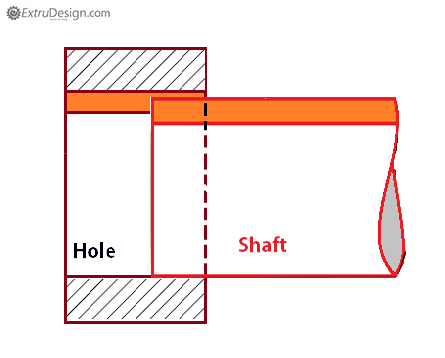
Transitional Fit
A transition fit mainly focuses on securely locating parts that would mate together and also be disassembled in an assembly. They are a compromise between both clearance and interference fits as they provide accuracy of location, like Interference Fits, while also providing some freedom just like clearance fits. Some of the notable Transitional Fits include [1];
| Example of Transitional Fit [3] |
|
Locational Clearance Fit
Locational Clearance Fits are primarily used for stationary parts that need to be freely disassembled. These fits are designed so that there is minimal clearance between parts. They are commonly used on parts such as bearings, bushings and any parts that are connected to a shaft such as pins. The coupled parts must still be fixed together mechanically to prevent any minor movements during assembly [2].
Locational Transition Fit
Locational Transition Fits are a compromise between both clearance and interference fits, where either a small amount of clearance or interference is allowed. They are mainly used for where accuracy of location is important for alignment purposes [2].
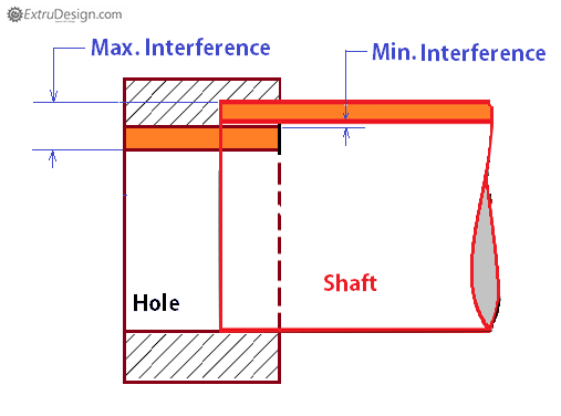
Interference Fit
Interference Fits are opposite to Clearance fits, where the minimum shaft diameter based on its tolerance is always larger than the maximum hole diameter. This fit is primarily used to fasten two mating parts together without the need for screws or wels. Friction is utilized to hold the parts together. Interference Fits between two parts are usually created by hydraulic presses or heat/freezing (shrink fits) [1].
| Example of an Interference Fit [3] |
|
Locational Interference Fit
Locational Interference Fits provide minimal interference between mated parts and mainly focus on the accuracy of location. These fits are used for parts that require precise alignment and these parts can be assembled and disassembled by using a press. This fit is the typical one used for steel, cast iron or brass assemblies [4].
Driving Fit
Driving are interference fits that are usually used with steel parts and they are the tightest fit that are usually with cast iron shaft/holes. They require higher assembly forced for creating these fits using a hydraulic press. They are commonly used to permanently mount gears to gears or bushings [4].
Force Fit
Force Fits are a permanent type of interference fits, where there is high interference between the shaft and holes. They are designed to maintain a constant pressure between the mating parts They are typically used for shaft/hole parts that face high forces or torques. Forced fits are usually done by heating the part and freezing the part to mate the parts together [4].
References
- J. R. Baleshta. Engineering Graphics & Design. (2020, Winter). ME 100. Waterloo, Canada: University of Waterloo.
- "Limits & Fits." Fractory. https://fractory.com/limits-and-fits/. (accessed Mar. 05, 2021).
- "What are the different types of Fits in Engineering." ExtruDesign. https://extrudesign.com/types-of-fits-in-engineering/. (accessed Mar. 05, 2021).
- "ANSI Standard Limits and Fits." Coban Engineering. https://www.cobanengineering.com/Tolerances/ANSILimitsAndFits.asp. (accessed Mar. 05, 2021).
Contributors:
| User | Last Update |
|---|---|
| Lesley Lang | 1215 days ago |
| Former user (Deleted) | |
| Former user (Deleted) | |
| Former user (Deleted) | |
| Former user (Deleted) |
Faculty Advisor: Chris Rennick, Michael Lenover (Alumni)