Gear Mounting
Table of Contents
Introduction
Proper mounting is critical to the function of any gear system. Gears have low tolerance for eccentricity (where the axis of the gear is offset from the axis of the shaft), axial misalignment (where the face of the gear is not normal to the shaft), and slop or free play in the mounting system. The most precise methods of fixing gears on a shaft include taper lock bushings, taper and friction fits, and high precision splines, but these add cost and make assembly more difficult. Set screws and keys are excellent solutions for many gear applications, but must be carefully used to avoid excessive wear or noise.
Bearing / Sliding Mounting
In manual transmissions, many gears rotating at different speeds share a common shaft. This reduces the size and complexity of the transmission, but it also means that the gears cannot be locked to the shaft. The gears have a precisely machined bore that runs on a ground or polished shaft, lubricated with oil. With the exception of idler gears, which simple change the direction of rotation, all gears that spin freely on the mounting shaft have some sort of feature that interfaces them with another gear or the shaft they are on. If a gear is made with a sintered powered metal or injection molding process, another gear can be added to the face of the gear. "Dog" teeth can also be used to selectively interface the gear with a splined coupling or another gear.
Bearings
More information can be found about bearings in this section of the Wiki : Bearings. The dynamic load rating on the bearing, free play, and sealing should be evaluated carefully to make sure that they are appropriate. If a helical gear is used, it will apply axial forces to the bearing, which could cause a plain roller bearing to fail.
Bushings
Bushing Selection should also be done carefully, with the same considerations as bearing selection. If possible, they can be lubricated directly at the contact area using a hole down the center of the shaft and cross holes which allow oil or grease to flow down the shaft and into the contact area.
| Sliding Gears and Dog Teeth | A hole down the center of this shaft allows oil to flow into the interface, as indicated. | Sintered Gear with Bushing Bore |
|---|---|---|
|
|
|


Spline Shaft Mounting
Splines are an excellent way to transmit torque and centre a gear for high power applications. They are used in automatic transmissions, in couplings between engines and gearboxes, and in machine tools where it is important to have concentricity and low amounts of slop in the system. Spline shafts can be made with many of the same processes as gears, including milling, shaping, grinding, and rolling. They can also be injection molded.
Involute Splines
Involute splines use the same shape as an involute gear tooth, which has a few key advantages. First, the angled sides of the teeth center the spline shaft in the mating part, improving the accuracy of the joint. Second, the smooth profile and radii of the involute form reduce the stress concentrations that parallel key splines experience. Involute splines are an excellent choice in high speed or low noise applications.
Parallel Key Splines
Parallel key splines have radial flanks and circular faces at the top and bottom of the spline tooth. This means that they do not self-center and if the corners are not relieved, they will have higher stress concentrations than involute splines.
Ball Splines
To minimize friction as the internal spline coupler moves along the shaft, ball splines use recirculating balls as the contact elements in a similar fashion to ball bearings. This allows a smooth linear movement.
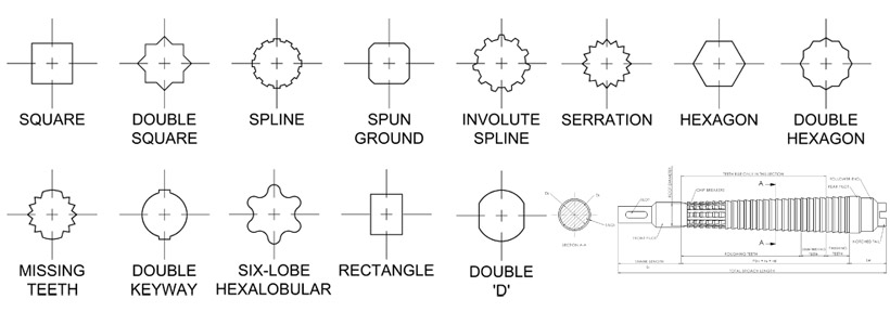
| Common Spline Profiles | Ball Spline |
|
|

Keyed Shaft Mounting
Keys are one common way to mount gears onto shafts- manufacturing is possible with common machine tools, the locking geometry is simple, and they can be repaired easily with hand tools if damaged. Typically, the keys are square or rectangular, so the keyway in the gear or pulley has sharp internal corners. A broach or shaper (using a single point tool to cut material along straight lines) is used to form the keyway in the pulley. This article, Keys and Keyways, from Engineering Product Design, contains additional reading material on the topic.
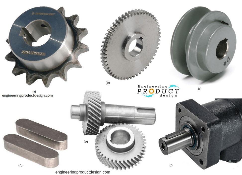
| Examples of keyed shafts for power transmission and gear mounting [ 9 ] |
|
Friction Fit Mounting
Tapered Shaft Mounting
Tapered shaft mounting eliminates many of the issues involved with keyed and splined mounting solutions. When the tapers on the gear and shaft are forced together, there is no play, very little radial and axial runout, and assembly is simple. A precise taper fit often requires grinding or polishing, which may increase the cost of the system. This article details some of the advantages of taper fits: Advantages of Taper Fitting.
Interference Fit Mounting (Also known as Straight Fit Mounting)
An interference fit is the simplest way of fixing a gear onto a shaft. It requires no extra components, but may require a press or hammer to assemble and disassemble. It also requires that the shaft and bore of the gear be precisely machined so that the tolerances of the interference fit are met. For most cases, an interference between 0.05 mm and 0.01 mm is sufficient, but the appropriate table of fits should be used to find the correct sizing and tolerances. For very large or small shafts, this rule does not apply. This article, Tolerances Associated with Gears, describes the design process in more detail.
Straight Fit vs. Taper Fit Gear |
|

Taper Lock Bushings
Taper lock bushings are a neat way to achieve zero-clearance fits without machining a taper on either part. The bushing consists of 3 parts: a tapered sleeve, which is split, a tapered collet, which collapses when force is applied to it, and a nut to draw the tapered nut into the collet. As the nut is tightened, the tapers force the sleeve to grow larger and the collet to shrink, applying a force to both parts. Friction holds the two parts together. The torque capability of this coupling depends on the nut torque and surface conditions, but there is no play in the system and it is quick to install.
Taper Lock Bushing from SDP / SI. Note the split sleeve and collet. |
|

Set Screw Mounting
For light loads and fast assembly, a set screw can be used to lock the gear onto the shaft. In most cases, the shaft is required to have a flat or divot where the set screw makes contact. This avoids raising a burr on the shaft, which would make the gear nearly impossible to remove. Brass or nylon tipped set screws can also be used to avoid marring the shaft if it is not possible to add a flat for the set screw. It's important to note that even if the shaft has a flat, the diameter of the set screw and tip geometry has a large effect on the allowable torque. If the set screw is small, the tip will see very high contact forces as the shaft tries to rotate relative to the gear, so it should be made as large as possible.
The amount of torque able to be transmitted by this mounting solution is highly variable - it depends on the surface condition of the gear bore, whether the assembly was lubricated prior to assembly, and how much torque the user applied to the set screw as they tightened it. If the set screw is not held in place with a second set screw or permanently secured with a thread-locking compound like Loctite, it can loosen over time, allowing the gear to run spin, which would destroy the gear and the shaft.
In most cases, a gear secured with a set screw will not be as well-centered as a gear secured with a friction fit or spline shaft. In most low speed and low torque applications that set screws are used for, this is fine, but if there is a large amount of clearance between the shaft and gear bore, the gears will not mesh smoothly because the effective center distance will change constantly, leading to wear and noise.
A pulley secured to a shaft using a set screw. Note the mark on the shaft flat. | |
|
|
|---|---|


References
[1] el bob, "Famco 100 Vertical Mill, Pancake Motor, VFD, Cold Start Problem," Practical Machinist.com, Dec. 29, 2019. [Online]. Available: https://www.practicalmachinist.com/vb/cincinnati-milacron-kearney-trecker-vn-usa-heavy-iron/famco-100-vertical-mill-pancake-motor-vfd-cold-start-problems-344262/. [Accessed November 9, 2020].
[2] True Gear and Spline Ltd., "Splined Shafts vs. Keyed Shafts," True Gear and Spline Ltd., Dec. 31, 2018. [Online]. Available: https://true-gear.com/splined-shafts-versus-keyed-shafts/blog.html. [Accessed: November 9, 2020].
[3] J. Kowalsky, R. Och, N. Weiss, "Side Fit Spline Profiles," Gear Solutions, March 1, 2004. [Online]. Available: https://gearsolutions.com/features/side-fit-spline-profiles/. [Accessed: November 9, 2020].
[4] Perry Technology, "Broaching," Perry Technology Solutions, 2016. [Online]. Available: https://www.perrygear.com/machining-services/broaching. [Accessed: November 9, 2020].
[5] J. Camillo, "Best Practices for Press Fit Assembly," Assembly, September 14th, 2017. [Online]. Available: https://www.assemblymag.com/articles/93984-best-practices-for-press-fit-assembly. [Accessed: November 9, 2020].
[6] B. Dengel, "Tolerances Associated with Gears," Gear Solutions, October 15, 2018. [Online]. Available: https://gearsolutions.com/departments/tooth-tips/tolerances-associated-with-gears/. [Accessed: November 9, 2020].
[7] Stock Drive Products Sterling Instruments, "Taper Shaft Bushings (metric)," Designatronics Inc, 2020. [Online]. Available: https://shop.sdp-si.com/catalog/?brand=sdp&cid=p849. [Accessed: November 9, 2020].
[8] M1 Seiko Co., Ltd, "Advantages of Taper Fitting," M1 Seiko Co., Ltd, 2010. [Online]. Available: http://www.m1-seiko.co.jp/craftsmanship_taper_e.html. [Accessed: November 9, 2020].
[9] Engineering Product Design, "Keys and Keyways," Engineering Product Design, 2019. [Online]. Available: https://engineeringproductdesign.com/knowledge-base/keys-keyways/. [Accessed November 9, 2020].
Contributors:
| User | Last Update |
|---|---|
| Lesley Lang | 1354 days ago |