Transformers
- Former user (Deleted)
- Mayurakhi Khan
- Former user (Deleted)
- Former user (Deleted)
Table of Contents
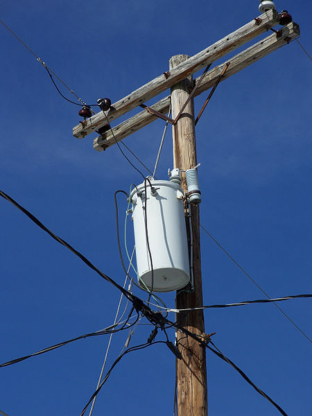
Distribution Transformer Mounted on a Utility Pole [1] |
|---|
|
Introduction to Transformers and their Purpose
Transformers are electrical equipment which can transform alternating current (AC) transmission voltages into much higher or lower voltages. Transformers address two issues which arise when trying to deliver electricity from power stations to users of electricity. Firstly, while power stations can generate enormous amounts of power, everyday household appliances and devices only need 110-250 volts. On the other hand, factories may require higher supplies of voltages than what the conventional household may need, which indicates that electricity needs ultimately differ widely depending on the application or the end user. Furthermore, much of the energy transferred from the power station to users may be lost - this lost power can be calculated with the power loss formula:
where stands for the transmission current and
stands for resistance of the transmission wire. Hence, delivering low-voltage, high-current electricity from a power plant to households is not a viable solution as most of the power will be lost, deduced by the fact that the current is squared in the power loss formula [2]. However, delivering high-voltage electricity to households is also not an option, as most appliances and electronics are not compatible with such high voltages.
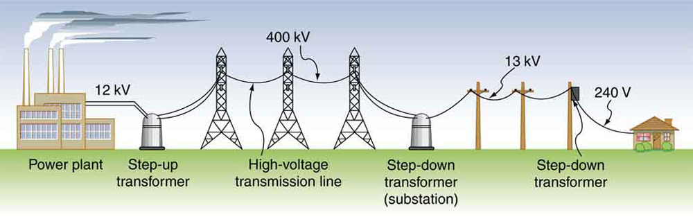
Transformers resolve both these issues by transforming power to high-voltages at the power plant, ultimately minimizing power loss through the shipment of high-voltage, low-current electricity and then retransforming voltages near the destination so that the electricity is suitable for each end use. For information concerning the conversion from AC to direct current (DC), please refer to the Full Wave Rectifier under the P-N Junction Node. An example visualization of how transformers may be used is provided below (Step-up and Step-down transformers are described in a later section):
Transformers at Various Stages of Electricity Delivery [3] |
|---|
|
How Transformers Work
Faraday's Law of Induction
Transformers are essentially an application of Faraday's Law of Induction, which states that the
Rate of change of flux linkage with respect to time is directly proportional to the induced EMF in a conductor or coil [4].
To put it simply, a change in the magnetic environment of a coil of wire will cause an electromotive force (EMF), or an electric current, to be induced in the coil [5]. The opposite is also true as a fluctuating electric current flowing through a wire can generate a magnetic field or "magnetic flux" around it [2]. The strength of this magnetic flux generated is directly proportional to the size of the electric current.
Faraday's Law can be mathematically interpreted through the formula [6]:
where the induced EMF,, is directly proportional to both the change in flux,
, and the number of turns in the coil,
, while being inversely proportional to the change in time,
. The negative sign indicates that the direction of the induced EMF is opposite to the direction of the change in magnetic flux [7]. This is a reference to Lenz's Law, which predicts the direction of an EMF induced by a changing magnetic field [7]. Therefore, keeping in mind Faraday's Law of Induction, by placing two coils where one has a fluctuating electric current, magnetic flux is created and hence an electric current can be "induced" in the second wire. This process of inducing a current in the second coil is known as mutual induction, or simply, electromagnetic induction. (Note the importance of using a fluctuating electric current, hence the need for AC instead of DC)
Mutual Induction
Mutual induction is the situation where a wire is within range of the magnetic field created by another wire with a fluctuating electric current, causing an "induced" EMF. These two wires are usually comprised of copper. The original current is called the primary current while the current created by mutual induction is called the secondary current. Voltage and number of windings associated with the first coil are referred to as the primary voltage and primary number of windings, respectively, whereas the secondary coil has a secondary voltage and a secondary number of windings. Electrical energy can be passed more efficiently through the use of a core, which is usually a highly permeable material, such as a soft iron bar, to more effectively channel flux [2].
Two Wires Wrapped Around a Core [8] |
|---|
|

Transformer Turn Ratio
Assuming an ideal transformer, the turns ratio of a transformer, or the ratio between the primary windings and the secondary windings, can indicate the secondary voltage, or the EMF induced [9]:
whererepresents the primary number of windings,
represents the secondary number of windings,
represents the primary voltage, and
represents the secondary number of windings. If the ratio is greater than 1, then the secondary voltage is less than the primary voltage. This is known as a Step-Down Transformer. If the ratio is less than 1, the secondary voltage is greater than the primary voltage. This is referred to as a Step-Up Transformer [2].
For instance, if the primary number of windings was 1000 and the secondary number of windings was 100, then the turns ratio would be 10:1, or just 10. It can be inferred that the secondary voltage would be less than the primary voltage. If given the primary voltage as 120V, the secondary voltage can be found:
Hence, the secondary voltage is 12V, considerably less than the primary voltage of 120V, and this aligns with our prediction.
Transformer Efficiency
The efficiency of a transformer is calculated by the ratio between the power measured at the secondary winding and the power measured at the primary winding - essentially power output and power input:
In ideal cases, the efficiency of an electrical transformer is between 94% and 96% [10].
Since a plain transformer does not incorporate any moving parts to transfer energy, there is no friction or windage losses [10]. However, copper losses can occur due to heat loss during the circulation of currents around the copper windings. Additionally, if the core is made of iron, iron losses can occur due to the "lagging of the magnetic molecules" that lie within the core [10]. This happens in response due to the alternating magnetic flux and ultimately results in friction, and hence, heat. Heat loss can be significantly reduced if the core is made of special steel alloys [10].
Types of Transformers
On the Basis of Purpose
Step-Up Transformers
Step-up transformers are transformers in which the number of secondary windings is greater than the number of primary windings, resulting in a voltage boost [2]. This type of transformer is commonly used right after the power plant, for long-distance, low-loss delivery of electricity.
Step-Down Transformers
Step-up transformers are transformers in which the number of secondary windings is less than the number of primary windings, resulting in a voltage reduction [2]. This type of transformer is commonly used right before final delivery of electricity to households and other places.
Step-up Transformer [11] | Step-down Transformer [12] |
|---|---|
|
|


Basis of Use
Power Transformer
Power transformers are transformers with a very high rating and are typically used to transmit electricity to the public electricity supply [10].
Distribution Transformer
Distribution transformers are transformers with a comparatively lower rating and are used to distribute electricity [10].
Power Transformer [13] | Distribution Transformers Mounted on a Utility Pole [14] |
|---|---|
|
|


References
[1] D. M. Gualtieri, Power Transformer. Wikimedia Commons, 2011.
[2] C. Woodford, “How do electricity transformers work?,” Explain that Stuff, 27-May-2020. [Online]. Available: https://www.explainthatstuff.com/transformers.html. [Accessed: 10-Mar-2021].
[3] OpenStax, “Transformers,” Lumen. [Online]. Available: https://courses.lumenlearning.com/physics/chapter/23-7-transformers/. [Accessed: 10-Mar-2021].
[4] “The Basics of Electrical Transformers,” D & F Liquidators, 07-Sep-2020. [Online]. Available: https://www.dfliq.net/blog/the-basics-of-electrical-transformers/. [Accessed: 10-Mar-2021].
[5] Faraday's Law. [Online]. Available: http://hyperphysics.phy-astr.gsu.edu/hbase/electric/farlaw.html. [Accessed: 10-Mar-2021].
[6] “Physics - Electromotive force,” University of Birmingham. [Online]. Available: https://www.birmingham.ac.uk/teachers/study-resources/stem/physics/electromotive-force.aspx#:~:text=Electromotive%20force%20(EMF)%20is%20equal,charge%20(Q)%20passing%20through. [Accessed: 16-Mar-2021].
[7] OpenStax, “Faraday’s Law of Induction: Lenz’s Law,” Lumen. [Online]. Available: https://courses.lumenlearning.com/physics/chapter/23-2-faradays-law-of-induction-lenzs-law/#:~:text=The%20minus%20sign%20in%20Faraday%27s,is%20known%20as%20Lenz%27s%20law. [Accessed: 16-Mar-2021].
[8] Two wires wrapped around Core. Explain that Stuff.
[9] “Transformer Basics and Transformer Principles of Operation,” Basic Electronics Tutorials, 27-Jan-2021. [Online]. Available: https://www.electronics-tutorials.ws/transformer/transformer-basics.html. [Accessed: 22-Mar-2021].
[10] D&F LiquidatorsD&F Liquidators has been serving the electrical construction materials needs for more than 30 years. It is an international clearinghouse, “The Basics of Electrical Transformers,” D & F Liquidators, 07-Sep-2020. [Online]. Available: https://www.dfliq.net/blog/the-basics-of-electrical-transformers/. [Accessed: 22-Mar-2021].
[11] C. Woodford, Step-Up Transformer. Explain that Stuff, 2020.
[12] C. Woodford, Step-Down Transformer. Explain that Stuff, 2020.
[13] P. Chernikhowsky, Flickr, 2009.
[14] Versageek, Utility Pole Transformers. Wikimedia Commons, 2007.
Contributors:
| User | Last Update |
|---|---|
| Mayurakhi Khan | 1215 days ago |
| Former user (Deleted) | |
| Former user (Deleted) | |
| Former user (Deleted) |
Faculty Advisors: John Thistle, Kim Pope, Michael Lenover (alumni)