Measuring Tolerances
- Former user (Deleted)
- Lesley Lang
- Former user (Deleted)
Table of Contents
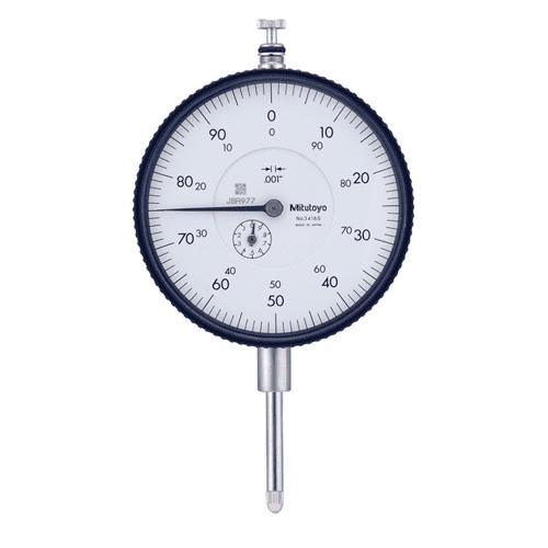
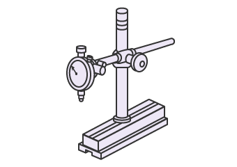
Dial Gauges (Dial Indicators)
A dial gauge (or dial indicator) can be used to measure surface height variation for many different parts, to see if they are within tolerance. This can be useful for measuring many different form, profile, orientation, locational, and runout geometric characteristics. When using dial indicators, the reference size is created by a gauge block [1].
| A Dial Gauge [2] | A Dial Gauge Configuration [1] |
 |
|
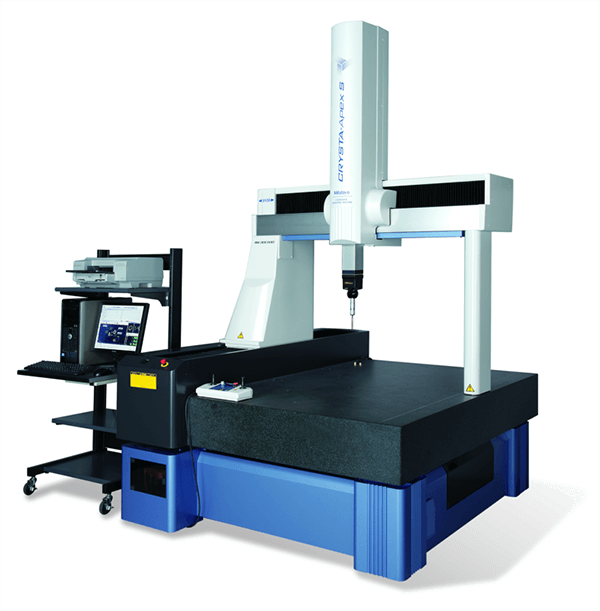
Coordinate Measuring Machine (CMM)
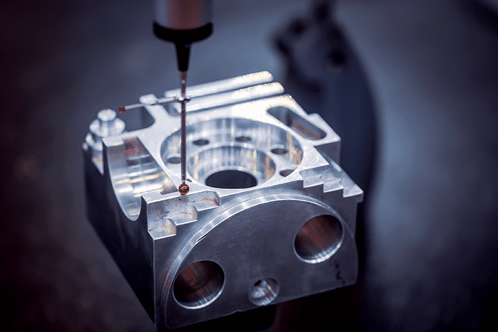
A Coordinate Measuring Machine (CMM) is typically used for making very precise measurements through a fully automated way [3]. They are able to take height, width and depth measurements using computer software, to see if they are within tolerance [4]. CMMs work similarly to that of CNC Machines, which allow for their high accuracy, flexibility and speed. Most of the GD&T characteristics can be measured by using CMMs and can provide more accurate readings compared to Dial Gauges. Coordinate Measuring Machines are either a contact model, which uses a probe to take measurements or a non-contact model, which uses lasers and cameras to obtain measurements [4]. Coordinate Measuring Machines are very expensive devices and also require a lot of experience/knowledge to use effectively for GD&T purposes, so they are more likely used for more complex GD&T characteristics such as the Profile Tolerances.
| A CMM Machine [5] | Close-up of CMM Probe [3] |
|
|
Measuring Form Tolerances
Straightness
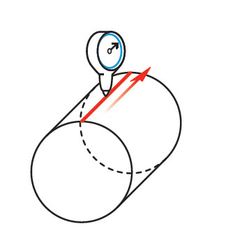
Surface straightness can be measured by running a gauge along a straight line of a part. The variation in height is measured by the gauge to see how straight the line is along the surface of the part [6].
| Gauging surface straightness [6] |
|
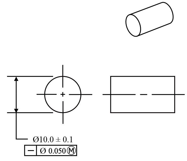
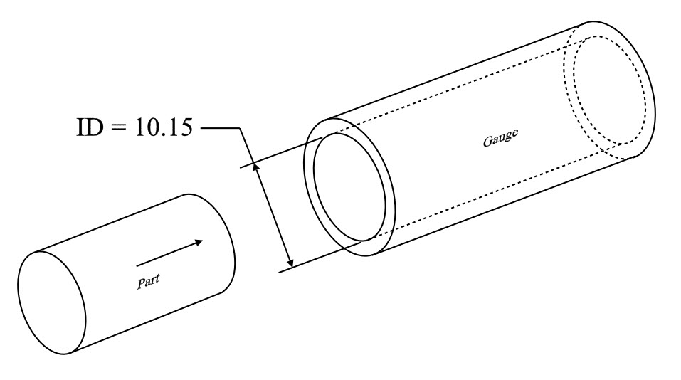
Axis straightness can be measured with a cylinder gauge. MMC (maximum allowable diameter of the part) is usually called out to gauge the part effectively, because the cylinder gauge determines if the part fits within its total allowance at MMC. The cylinder gauge ID represents the maximum virtual condition of the part. When the part diameter is smaller than MMC, a bonus tolerance can be added, which equals the difference between MMC and the actual size [6].
| Gauging axis straightness [6] | |
|
|
Flatness
Flatness can be measured by running a height indicator or probe over the surface. The most common measurement technique is to place the surface in reference face down on the surface plate. Then place a dial indicator in a way such that its tip comes through a hole on a surface plate. Then drag the surface over the indicator tip. If the FIM (full indicator movement) of the indicator is larger than the flatness tolerance, the part has broken the flatness control tolerance and is not up to specification [7].
| Diagram of typical Flatness Measurement Method [8] | Another method of Flatness Measurement (using CMM) [7] |
|
|


Cylindricity
Since the cylindricity tolerance focuses on the distortion of the cylindrical form, the best way to measure it is to place the part on a turntable. A measuring device, ideally a height gauge can then contact the part at the circular element that needs to be measured. As the part is rotated, the height gauge will move up and down, capturing the variation of the surface of the circular element [9]. This data can then be plotted onto a polar graph by computer to see if the circular element withholds the tolerance. The total variation of the height gauge must be less than the tolerance value in the feature control frame for the part to meet specifications [10].
| Diagram of typical Cylindricity Measurement [10] | Polar Graph Example [10] |
|
|


Measuring Profile Tolerances
Profile of a Line
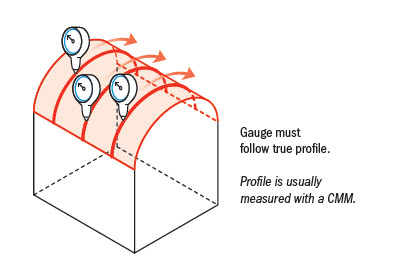
Since the profile of a line tolerance can be very complex, the best way to measure it is by using a Coordinate Measuring Machine (CMM). Initially, the number/locations of measurement points should be specified in the drawing for the part, since there are an unlimited amount of 2D cross-sections [11]. Then a reference plane is set and the stylus can be placed on the indicated measurement points. The deviation from the target element and the reference plane can then be measured and checked to see if it fits within the specified tolerance by the tolerance value [12].
| Profile of Line Measurement with CMM [12] | Profile of Line Measurement with Dial Gauge [11] |
|
|


Profile of a Surface
Since the profile of a surface tolerance can be very complex, the best way to measure it is by using a Coordinate Measuring Machine (CMM). The CMM compares the 3D scan of the profile with the dimensions of the profile in the drawing, to see if it is within tolerance. A gauge can be used, instead of a CMM, if the surface is simple (like a radius or corner) and the gauge can maintain the same distance from surface as it rotates around it. The gauge is used to trace the part along the surface [13].
| Complex profile of a surface measurement [13] | Simple profile of a surface measurement [13] |
|
|

Measuring Orientation Tolerances
Angularity
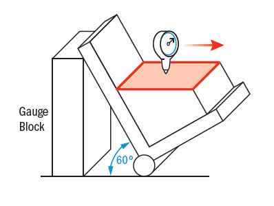
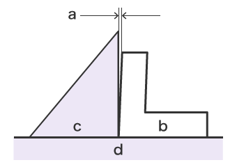
Angularity is measured after tilting the part to the dimensioned angle, using a sine bar to constrain it, so that the reference surface is parallel to the horizontal. When the reference surface is horizontal, a gauge can be used to measure flatness and ensure the variation does not fall outside the tolerance zone [14].
| Angularity measurement [14] |
|
Perpendicularity
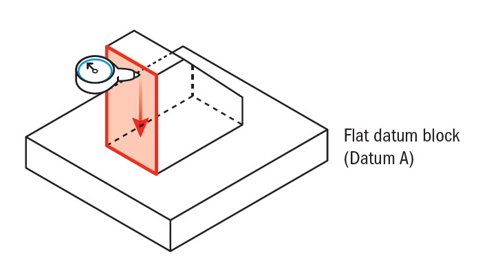
To measure surface perpendicularity, a gauge can be run across the reference surface, always 90 degrees from the datum surface. The value from the gauge can be used to determine whether the part is within its tolerance zone [10]. Another way is to hold a square ruler to the surface and measure the gap between the ruler and the part surface using a pin or feeler gauge. The most accurate way is to use a CMM (Coordinate Measuring Machine) [15].
| Measuring surface perpendicularity (height gauge method) [15] | Measuring surface perpendicularity (square ruler method) [16] |
|
|
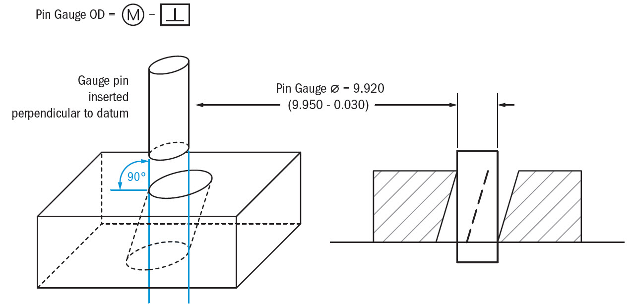
To measure axis perpendicularity, MMC (Maximum Material Condition) is usually called out so that the hole gauge (for a positive feature) or pin gauge (for a negative feature) diameter can be calculated. A bonus tolerance is added when the part is less than MMC, and it equals the MMC size minus the actual size of the part. The bonus can be added to the the GD&T tolerance, widening the perpendicularity tolerance [15].
Pin Gauge Ø = Min Ø of Hole (MMC) - Perpendicularity Tolerance
Hole Gauge Ø = Max Ø of Pin (MMC) + Perpendicularity Tolerance
| Measuring axis perpendicularity of a hole [15] |
|
Parallelism
The measurement of parallelism is similar to that of flatness, except all measurements are referenced to a datum surface. A dial gauge can be swept across the surface and the difference between the largest and smallest measured values represent the parallelism value. If the parallelism value exceeds the tolerance value set by the feature control frame, the part is not up to specification [17].
| Labelled Diagram of Parallelism Measurement with Dial Gauge [18] |
|

Measuring Locational Tolerances
Position
To measure the Positional tolerance of an entire feature, the feature's center position is compared to the center of the datum surface, by the use of x and y coordinates. The coordinates that represent the center location of the feature is called the Actual X & Y coordinates while the center location of the datum surface is called the True X & Y coordinates. To obtain the Actual X & Y coordinates, a CMM can be used to simply measure how far it is from the end of a datum surface. Comparing the Actual X & Y coordinates to the True X & Y, with the use of a simple formula will give the current positional tolerance. That equation is shown below. If the resulting value from the formula is greater than the Position tolerance value, then the part is not within specification [19].
| Measurement of Position Tolerance and the Used Formula [19] |
|

When gauging hole locations (internal features) to fit within the specified positional tolerance, another simple equation can be used to get obtain the position of the hole. The equation is as follows; Gauge = Min Diameter of Hole (MMC) - Position Tolerance.
| Gauging of Hole Locations [19] |
|

Concentricity
The easiest way to measure Concentricity is the use of a dial gauge and horizontal turntable [15]. The part can be attached to the turntable with the dial gauge touching the circumference of the axis (circumference of the circular part). Then the part can be rotated and the maximum and minimum runout values will be reported by the dial gauge. The greatest difference between the maximum and minimum values is used as the concentricity value [20]. If this value exceeds the tolerance value, then this part is not up to specification. This method of using a dial gauge is not the most efficient as it is not the most accurate. To have the most accurate gauging, a CMM or other computer measurement device should be used, but this is a very complex process that requires a lot of time and skill to do.
| Concentricity Measurement with a Height Gauge [20] |
|

Symmetry
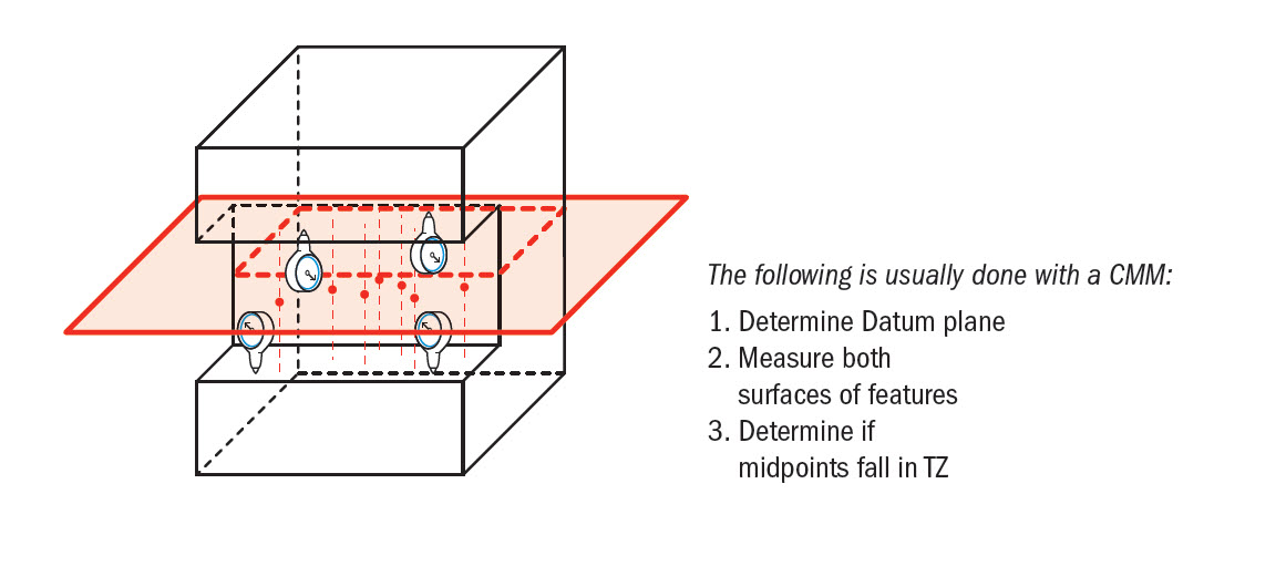
Symmetry is usually measured with a CMM, rather than a gauge, due to the use of a virtual plane. Symmetry is very difficult to measure at it is complex and sometimes inaccurate. A CMM is set up to calculate the theoretical midpoint datum plane and measure both surfaces involved to calculate the actual midpoints. Whether or not the part is within tolerance depends on where the actual midpoints are located relative to the calculated datum plane [21].
| Symmetry Measurement [21] |
|
Measuring of Runout Tolerances
Circular Runout
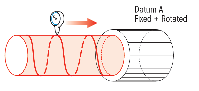
Circular runout can be measured using a gauge on the referenced surface. The datum axis is created by fixing all datum points and rotating the central datum axis. The part is then rotated around this datum axis and deviation is measured using the gauge. To meet the specified circular run-out tolerance, the measurement created at that point on the specified circumference must be within the tolerance zone. This runout is only measured on an individual section compared to doing the entire cylinder (like Total Runout) [22].
| Circular Runout Measurement on Turntable [23] |
|

Total Runout
Total runout can be measured by fixing the datum axis (or other type of datum) using a spindle or set of V-blocks, rotating the part, and running several gauges across the surface as it rotates. The gauges must be linked to take the measurements relative to each other. To measure total runout with one gauge, a gauge can be moved in the direction parallel to the datum, while the part is rotating. For both of these methods, if the gauge(s) varies more than the tolerance value allows, the part is not acceptable [19].
| One-gauge method of measuring total runout [24] |
|
References
- Anonymous. "Measuring Instruments." Keyence. https://www.keyence.com/ss/products/measure-sys/gd-and-t/measure/tool.jsp (accessed Mar. 15, 2021).
- B. Warfield. "Dial Indicators & Dial Test Indicators." CNC Cookbook. https://www.cnccookbook.com/dial-indicators-dial-test-indicators-easy-guide-2018/ (accessed Mar. 12, 2021).
- "Complete CMM Machine and Measurement Guide." CNC Cookbook. https://www.cnccookbook.com/complete-cmm-machine-and-measurement-guide-pc-dmis/. (accessed Mar. 17, 2021).
- "Coordinate Measuring Machines." Keyence. https://www.keyence.com/ss/products/measure-sys/measurement-selection/type/3d.jsp. (accessed Mar. 17, 2021).
- "Everything you should know about a Coordinate Measuring Machine." Roche Industry. https://www.rocheindustry.com/coordinate-measuring-machine/. (accessed Mar. 17, 2021).
- Anonymous. "Straightness." GD&T Basics. https://www.gdandtbasics.com/straightness/ (accessed Mar. 1, 2021).
- "Flatness." GD&T Basics. Available: https://www.gdandtbasics.com/flatness/. (accessed Jan. 22, 2021).
- "Flatness". Engineering Essentials. Available: http://www.engineeringessentials.com/gdt/flatness/flatness.htm. (accessed Jan 22. 2021).
- "Cylindricity." GD&T Basics. https://www.gdandtbasics.com/circularity/. (accessed Feb. 23, 2021).
- "GD&T - Cylindricity." Available: http://www.engineeringessentials.com/gdt/cylindricity/cylindricity.htm. (accessed Feb. 23, 2021).
- "Profile of a Line." GD&T Basics. https://www.gdandtbasics.com/profile-of-a-line/. (Accessed Feb 22, 2021).
- "Measuring the Profile Tolerance of Line." Keyence. Available: https://www.keyence.com/ss/products/measure-sys/gd-and-t/form-tolerance/profile-line.jsp. (accessed Feb. 24, 2021).
- Anonymous. "Profile of a Surface." GD&T Basics. https://www.gdandtbasics.com/profile-of-a-surface/#:~:text=Description%3A,an%20advanced%20curve%20or%20shape.&text=Usually%2C%20when%20surface%20profile%20is,to%20give%20the%20acceptable%20range. (accessed Mar. 1, 2021).
- Anonymous. "Angularity." GD&T Basics. https://www.gdandtbasics.com/angularity/#:~:text=Gauging%20%2F%20Measurement%3A,the%20now%20horizontal%20reference%20surface. (accessed Mar. 3, 2021).
- Anonymous. "Perpendicularity." GD&T Basics. https://www.gdandtbasics.com/perpendicularity/ (accessed Mar. 8, 2021).
- Anonymous. "Measuring Perpendicularity." Keyence. https://www.keyence.com/ss/products/measure-sys/gd-and-t/orientation-tolerance/perpendicularity.jsp (accessed Mar. 8, 2021).
- "Parallelism." GD&T Basics. https://www.gdandtbasics.com/parallelism/. (accessed Feb. 23, 2021).
- "Measuring Parallelism." Keyence. Available: https://www.keyence.com/ss/products/measure-sys/gd-and-t/orientation-tolerance/parallelism.jsp#:~:text=Using%20a%20Dial%20Gauge,-a%20Target&text=Move%20the%20target%20or%20height,height. (accessed Feb. 23, 2021).
- "True Position." GD&T Basics. https://www.gdandtbasics.com/true-position/. (accessed Feb. 24, 2021).
- "Measuring Concentricity." Keyence. Available: https://www.keyence.com/ss/products/measure-sys/gd-and-t/location-tolerance/concentricity.jsp. (accessed Feb. 23, 2021).
- Anonymous. "Symmetry." GD&T Basics. https://www.gdandtbasics.com/symmetry/ (accessed Mar. 3, 2021).
- "Runout." GD&T Basics. Available: https://www.gdandtbasics.com/runout/. (accessed Feb. 22, 2021).
- "Run-out Tolerance (Run-out Deviation)." Keyence. Available: https://www.keyence.com/ss/products/measure-sys/gd-and-t/type/run-out-tolerance.jsp. (accessed Feb. 22, 2021).
- Anonymous. "Total Runout." GD&T Basics. https://www.gdandtbasics.com/total-runout/ (accessed Mar. 5, 2021).
Contributors:
| User | Last Update |
|---|---|
| Lesley Lang | 1228 days ago |
| Former user (Deleted) | |
| Former user (Deleted) | |
| Former user (Deleted) | |
| Former user (Deleted) |
Faculty Advisor: Chris Rennick, Michael Lenover (Alumni)