LiDAR
Table of Contents
LiDAR Sensor View [1] |
|---|
|

Introduction to LiDAR
LiDAR (also LIDAR and Lidar), Light Detection and Ranging, is a remote sensing technology founded on the principle of TOF, or time of flight. LiDAR uses laser light to illuminate surrounding surfaces and then collects the reflections of the emitted laser light. The time of flight of the laser light is measured and, in conjunction with the speed of light, the distance of the surface from the LiDAR sensor is calculated [2][3]. (Note LiDARs may use ultraviolet, visible, or near-infrared light)
LiDAR has several scientific uses as well as engineering applications. Large scale projects may use LiDARs to survey or map land and to ultimately produce accurate environments, shorelines, maps, treetop data, or digital elevation models [3]. LiDAR is also used for autonomous vehicles and robots for collision prevention. Notable consumer products that use LiDAR are the 2nd and 4th generation iPad Pros [4]. In this particular project, LiDARs are put to the test by using them to track golf balls - small and high speed airborne objects.
LiDAR Map of Lynnhaven Inlet, Virginia [5] | LiDAR Sensor Technology on 2020 iPad Pro [4] |
|---|---|
|
|


Velodyne LiDAR VLP-16 | User Manual
"The VLP-16 sensor uses an array of 16 infra-red (IR) lasers paired with detectors to measure distances to objects" [6]. The array of lasers spins rapidly and each laser is fired approximately 18,000 times per second, resulting in 16 "cones" if all the data points are compiled [6]. The vertical angle between adjacent lasers is 2° where, if the horizontal is considered 0°, then the lowest-angled laser is -13° and the uppermost-angled laser is 13°. The horizontal angle, or angular resolution, between each laser shot, on the other hand, depends on the rotations per minute (RPM). The angular resolution on the VLP-16 varies anywhere from 0.01° to 0.04°, inclusive. The calculation for the angular resolution can be found under this section.
Snapshots of accurate mathematical models generated in MATLAB below depict the laser emission patterns of the Velodyne LiDAR VLP-16:
(Note MATLAB code can all be found in the MATLAB Code section.
| Side view of 16 lasers being emitted from the LiDAR sensor | Close-up view of 4 of the 16 lasers emitted | Full emission pattern of laser emission of VLP-16 when spinning (Note the horizontal gaps between each individual laser point are much smaller in reality but were increased in MATLAB due to computational limitations) |
|---|---|---|
|
|
|


Connecting to the Velodyne LiDAR VLP-16
The Web Interface allows users to configure certain settings of the VLP-16 such as FOV and RPM while software from Velodyne known as VeloView will allow users to stream and view the laser points, create a recording, review a recording, extract data points, etc. This section will provide instructions on how to connect to the VLP-16 and access its relevant configuration software. To connect to the Velodyne LiDAR VLP-16, the following is required:
Velodyne LiDAR VLP-16, its Interface Box and its power adapter |
| ||
Windows based laptop with Ethernet OR Mac with OSX version 10.8-10.9 with Ethernet OR Linux device with Ethernet OR a hub/adapter with an Ethernet port that connects to the device if the laptop does not have an Ethernet port (Note the instructions on this topic will solely be for Windows based devices) |
| ||
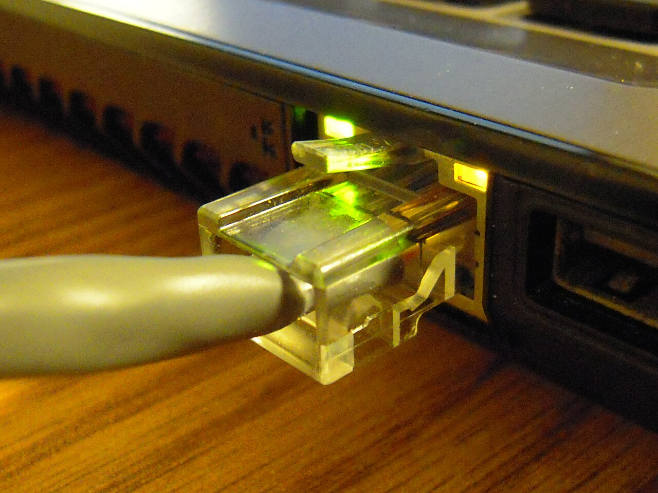
Ethernet (RJ45) Cable |
|


Install VeloView for your computer here
VeloView

- Connect the power adapter to the VLP-16's Interface Box; two green LEDs in the Interface Box should light up
- Connect one end of the Ethernet cable to the Interface Box and one end to the device with VeloView installed
- Open the computer's Network Connections page
- Select the applicable Ethernet adapter and ensure that it is enabled
Open Properties > Internet Protocol Version 4 (TCP/IP) > Use the following IP address
Internet Protocol Version 4 Settings (Windows)

Use the following IP address, subnet mask, and Web Interface address depending on the applicable case:
If your VLP-16 was previously used by the IDEAs Clinic and was borrowed from WATonomous,
- Set IP address to 169.254.0.19
- Set subnet mask to 255.255.255.0
- Enter 169.254.0.102 in your web browser to access the VLP-16's Web Interface
Else:
- Set IP address to 192.168.1.XXX where XXX is any number from 2 to 254 except 201
- Set subnet mask to 255.255.255.0
- Enter 192.168.1.201 in your web browser to access the VLP-16's Web Interface
Important: Default Gateway and DNS can be left empty. Your existing wireless Internet connection may need to be disconnected/disabled in order to access the Web Interface. Ensure you reset the settings for the Ethernet adapter after using the VLP-16 to automatically obtain an IP address and connect through wired Internet in the future.
The following Web Interface should appear in your browser:
LiDAR Web Interface

Basic Settings/Functions of the Web Interface
Referring to the image in the previous section depicting the Web Interface, descriptions for key features which are crucial for the golf project have been listed below:
Return Type
Strongest: Sensor provides only the strongest detected return.
Last: Sensor provides only the last (temporally) detected return.
Dual: Sensor provides both the strongest and last returns. If the last is also the strongest, the sensor provides the second-strongest return. If only one return is detected, the two values will be identical. [6]
For more information, consult pages 33-36 of the VLP-16 user manual linked at the title of this section.
Motor RPM
The motor RPM (Rotations per Minute) controls how fast the motor emitting the lasers will spin measured in RPM. This value can be set between 300 and 1200 inclusive in increments of 60. Use 1200 for optimal results when trying to capture fast-moving objects.
FOV Start and End
Sets the FOV (Field of View) values for the VLP-16 with the maximum FOV start and end values being 0 and 359, respectively.
Basic Settings/Functions of VeloView
Descriptions for key features of VeloView which are crucial for the golf project have been listed below:
Using Sensor Stream
The Sensor Stream function allows users to see the emitted lasers interacting with the surrounding environment in real time. To use the Sensor Stream, Open VeloView > File > Sensor Stream... > VLP-16
Recording a Scene
To record a scene with the VLP-16, select the Record button on the toolbar. To stop the recording, press the Stop button. This recording will be saved as a .pcap file and can be reviewed with VeloView.
Reviewing a Scene
To review a scene, Open VeloView > File > Open > Capture File... The perspective can be freely changed and each individual frame can be reviewed using the Seek Backward and Seek Forward buttons.
Viewing Data of Laser Points
VeloView allows users to view data of various categories collected from either Sensor Stream or from Recordings. Press Ctrl + T or select the small spreadsheet icon from the toolbar. Some important categories of data include:
- X, Y, Z
- X, Y, and Z coordinate positions of a reflected laser point relative to the VLP-16
- Azimuth
- The horizontal angle of a particular reflected laser point starting from the 0° position of the VLP-16 and measured in the hundredths of a degree
- Distance_m
- The distance of a reflected laser point from the VLP-16 measured in meters
In order to view only a few, selected points from the scene, select the Select All Points button from the toolbar and drag and release on the scene to select individual points. Then, open the Spreadsheet and select the Show only selected elements button at the top of the spreadsheet.
Extracting Data from VeloView
In order to extract data from VeloView as a .csv, first open up a Capture File as detailed in Reviewing a Scene and then go to File > Save As > Save CSV... From here, you can select to extract data from the Current frame, All frames, or from a selection of frames.
Golf Project Implementation
Within the Golf Project, the LiDAR sensors are used for the "Tracking and Simulation of a Golf's Ball Trajectory" objective but also work in conjunction with the high-speed camera component. While the VLP-16 is normally used upright to create 16 "vertical cones," the sensor can also be oriented on its side so that the lasers spin either in the direction parallel to the golf ball's trajectory, or perpendicular to the direction of the golf ball's trajectory. The ultimate goal of the golf project is to implement a multi-LiDAR tracking system at golf courses which can track golfers' shots and provide performance analytics and visualizations of their shots through software such as a mobile app. This section discusses the factors that need to be considered when using a LiDAR sensor for this type of purpose as well as the current progress of this implementation.
Independent Variables of the LiDAR Sensor Crucial for the Golf Project
Ignoring external factors which could affect the VLP-16 in an outdoor setting, the VLP-16 has independent variables that may influence the number of intersections found. For example, the RPM setting changes how fast the internal motor spins, ultimately increasing/decreasing the distance between two horizontally fired lasers. At the highest RPM setting of 1200, more of the golf ball’s trajectory may be identified but detection at farther distances becomes much less probable due to the large angular resolution between two adjacent lasers. On the other hand, at the lowest RPM setting of 300, while the sensor is more capable of identifying small objects at larger distances, the general probability of it catching the high-speed golf ball is much lower.
Furthermore, instead of simply utilizing the LiDAR sensor upright, it can also be used on its side so that the lasers are fired either perpendicular or parallel to the flight of the golf ball. With the perpendicular configuration, we theorized that while a smaller section of the golf ball’s lengthwise trajectory would be covered, the LiDAR sensor would be able to reliably identify the golf ball a few times. On the other hand, while the parallel configuration of the sensor can cover a much larger portion of the golf ball trajectory’s horizontal length, there is a chance that the golf ball can pass through the large, 2° horizontal gaps between laser firings. Our initial proposal assumed the use of 4 LiDAR sensors, one placed near the tee box, two spaced evenly between the tee box and the green, and one placed near the green. In this initial proposal, the two middle LiDAR sensors were placed in the perpendicular orientation but according to our simulations, the perpendicular orientation proved to actually be less reliable. The simulations can be tested through the MATLAB code linked in the Github repository at the bottom.
Calculating the Distance Where Golf Balls Cannot Be Accurately Detected
When taking into consideration the angular resolution (angle created by two horizontally fired lasers) of the LiDAR sensor, a theoretical limit to the VLP-16's detection of golf balls can be found. While there is the chance that the LiDAR sensor can detect a golf ball at very large distances, once the horizontal gaps between two adjacent lasers become the size of the golf ball, it becomes theoretically difficult for the sensor to reliably detect the golf ball.
Angular Resolution can be calculated by:
where 55.296e-6 is the time in seconds between two adjacent, horizontal laser firings. To calculate the radius of the laser at which the horizontal gaps become the size of a golf ball, we use the following formula:
where sind is the MATLAB syntax for evaluating sine in degrees. At 1200 RPM, when the horizontal gaps are expected to be the largest relative to other RPMs, the gaps between horizontal lasers become the size of the golf ball's diameter at 6 meters away from the sensor whereas at the lowest RPM setting of 300, the gaps of the golf ball's diameter appear at about 24 meters away. It should be noted that these calculations pertain to the horizontal gaps between adjacent, horizontally fired lasers with angular resolutions varying from 0.01° to 0.04° but if we consider the 2° vertical angular resolution between the 16 vertical lasers, the probability of identifying the golf ball at farther distances becomes much smaller due to the larger angular resolution.
Update on Progress of LiDAR Technology Implementation in the Golf Project
Unfortunately, after running multiple simulations using the MATLAB code written (linked at the bottom), it was found that very few points of the golf ball's trajectory was actually identified despite using multiple LiDAR sensors within the MATLAB simulation. The golf ball's trajectory was calculated using multiple factors, including lift, drag, gravity, spin, etc. and intersections with the golf ball's position were found with multiple, extremely accurate replications of the VLP-16. A full report on information pertaining to the golf project as well as details of the difficulties pertaining to LiDAR sensor implementation, ultimately leading to the decision to pursue other sports, is linked here: Golf Project LiDAR Tracking Report.pdf
MATLAB Code
Github repository for all VLP-16 related simulations: Eddy-M-K/MATLAB-LiDAR: VLP-16 LiDAR + Golf ball trajectory Simulation (github.com)
References
[1] LiDAR Sensor View. Clearpath Robotics.
[2] N. O. and A. A. US Department of Commerce, “What is LIDAR,” NOAA's National Ocean Service, 01-Oct-2012. [Online]. Available: https://oceanservice.noaa.gov/facts/lidar.html. [Accessed: 14-Jan-2021].
[3] “Lidar,” Wikipedia, 06-Jan-2021. [Online]. Available: https://en.wikipedia.org/wiki/Lidar. [Accessed: 14-Jan-2021].
[4] iPad Pro captures stunning photos and 4K video, and now includes a 10MP Ultra Wide camera. Apple.“
[5] A lidar map of Lynnhaven Inlet, Virginia. National Ocean Service.
[6] VLP-16 User Manual.” Velodyne, San Jose.
[7] VLP-16. Velodyne LiDAR.
[8] A twisted pair cable with an 8P8C modular connector attached to a laptop computer, used for Ethernet. Wikimedia Commons.
[9] Blue ethernet cable. Wikimedia Commons.
Contributors:
| User | Last Update |
|---|---|
| Mayurakhi Khan | 1343 days ago |