Main types of industrial robots
| Cartesian | Cylindrical | Delta | Articulated | SCARA | |
|---|---|---|---|---|---|
| Image |
|
|
|
| |
| Feasibility for rover? | No | Maybe | No | Yes | No |
| Reason for feasibility? | To big, cannot easily extend out of its frame | Similar to SCARA. also need a level surface to work effectively excellent horizontal reach, poor vertical reach primarily used for top down operations | end effector maintains orientation, used for top down operations exclusively | Fantastic reach small footprint (comparatively) | used for top down operations, breaking this design theory to accommodate. would defeat the purpose of a SCARA arm. Cannot guarantee the levelness of the rover during operation, again defeating the purpose. Cannot easily extend below the base fixture, height limited by stroke of vertical axis. We are not exclusively doing pick and place so no need for a pick and place bot. |


Articulated arm wins, its what every other rover has anyways (except for Perseverance's sample handling arm but that's a different level - science mechanism?)
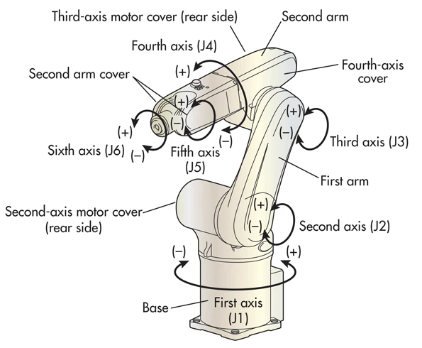
Topology Ideas for Articulated Arm

https://www.hindawi.com/journals/complexity/2017/5156264/
Note that the above arm is designed for measuring purposes, so it may not be suitable for high loads. It is interesting to note that joint 3 and 5 can rotated. Most industrial robots only have joint 5 that can rotate. and another joint after joint 6.


The above patent is a claw for a surgical arm, this one is interesting as the actuator is no where is sight, it is a cable driven claw.


 https://patents.google.com/patent/US8958916B2/en?q=robotic+arm+-surgical&oq=robotic+arm+-surgical


Top Performing URC Arms
The following information is taken from lurking SAR submission videos. Actual arm details may vary in real life, as there is only so much you can gather from a video
2019 Rovers: (2019 was last competition year, so it gives more context as to how these arms performed)
Teams are ordered based on overall score, not score for equipment/delivery missions. The true order of best performing arms may slightly vary, but since the arm is used in two missions overall score was taken
| Placement | Team/University | Arm Type | DoF | Joint Drives / Notes on Joints | Construction | End Effector | Vision |
|---|---|---|---|---|---|---|---|
| 1 | IMPULS/Kielce | Articulated | 6 | -Strain Wave (doesn't specify if custom or stock) (SHEEEESH) | -Looks like mainly a mix of box and round tube aluminum for shoulder/bicep -Multiple plastic parts on wrist/end effector | -Two aluminum fingers -Same fingers used for all missions -Claw rotation is driven by single motor (not differential) -No allen key attachment (grabbing screwdriver instead) | -One Wrist cam -One claw facing cam |
| 2 | Ryerson Rams | Cylindrical | 6 | -Linear axis used on forearm (its like a piston forearm, hard to tell what drive they used for this but its probably regular gearing) -Regular spur gear drives used on wrist/claw -Belt drives used on shoulder | -Carbon fiber tubing is used on the z axis articulating shoulder -The rest of the arm (forearm, claw) seems to be a mix of round and square aluminum tubing, with minimal or no 3D printed parts noticed | -Four finger aluminum(?) gripper on claw used for all missions -Claw rotation is driven by single motor (not differential) | -Couldn't tell from SAR video |
| 3 | Stanford Student Robotics | Scara | 6 | -Belt drives on larger arm joints Regular gearing on claw (i think, can't tell but it looks just like regular spur gearing) | -Pretty much exclusively aluminum box tube -Shit ton of 3D printed parts for all the belt drives | -Lead screw is used to make claw non backdriveable for better gripping (or so they claim) -Claw housing looks like its assembled from laser cut fiberboard, and actual two finger grippers are 3D printed -Finger grippers are swappable and have different designs for each mission (science, equipment, delivery) -they have a pencil attachment to operate the keyboard, but it doesn't look like they have an allen key attachment -single motor drives claw rotation (not differential) | -Couldn't tell from SAR video |
| 4 | PCz Rover Team / Czestochowa | Articulated | 5 | -Chain drive for shoulder joint -Regular spur gears used to drive wrist | -Looks like pretty much exclusively made from aluminum box tube with a bunch of welded flanges -Carbon fiber tubing used on other parts of their rover, but doesn't look like its on arm | -Technically two fingers constructed from aluminum as grippers, but there is a cut in the middle of the gripper allowing for four points of contact with items they grab -Different grippers used to collect soil samples (also made from aluminum) -Single motor drives rotation of claw (not differential) | -Gimbal system mounted high above wrist |
| 5 | Missouri | Articulated | 6 | -Looks like they used belt drives everywhere except for wrists -Not too sure what to call thier turntable. It looks like 3/4 of a differential joint, with one bevel gear on the bottom and two on the left/right but non on the top | -Key structural components made from carbon fiber, and mated parts constructed from aluminum | -They used a differential wrist with custom 3D printed gears -Two 3D printed gripping fingers -One interesting thing is that they use what looks like a sharpie end fired like a piston to interact with the keyboard -Entire end effector is double sided (one side for grippers, another side for this big end effector tool with different tool attachments) | -Couldn't tell from video |
| 6 | Cornell Mars Rover | Articulated | 6? maybe 5.. idk if arm base rotates from vid | -Belt driven arm base. I'm guessing they use belt drivers on other parts of the arm too, but its hard to tell -Worm gears used everywhere on wrist | -Aluminum sheets for the shoulder joint -Looks like maybe fibgerglass(? or painted wood lol) U-Channel to serve as forearm | -Two 3D printed grippers -Continuous rotation achieved through worm gear (not differential) -There are custom screwdrivers mounted to the frame of the chassis (like in a pocket) that the arm picks up to use for missions -They might be using springs to reduce backlash? | -Wrist Cam |
| 7 | Michigan Mars Rover Team | Articualted | 7! | -I can't really tell what drives they use (they don't say). I think it may be cycloid, as thats what they use in 2021 an the housing on stepper motors looks like it might house a cycloid drive? | -Carbon fiber box tube sections for all limbs, with machined aluminum at mated joints | -Lead screw driven two finger end effector -Also has the solenoid to interact with keyboard -Has slot for allen key attachment | -Wrist cam |
| 8 | Mars Rover Manipal | Articulated | 6 | -Arm is partially controlled by two linear actuators -No information in video or website on drives used for other joints sadly | -Constructed from carbon fiber tubing and aluminum parts for mating | -Two split aluminum grippers allowing for 4 points of contact with rubber grip pads -Differential wrist drives rotation using bevel gears | -There are multiple camera feeds for claw operations |
| 9 | Nova Rover / Monash | Articulated | 6 | -Belt drives and 24v linear actuators are used | -Constructed from aluminum sheets that have cutout trusses | -End effector has three 3D printed fingers that are spring loaded -Claw rotation is 360 degree and driven by single motor | -Can't tell from video |
| 10 | BYU MARS ROVER / Brigham Young | Artciulated | 6 | -Bevel gearbox on wrist -very few details on arm in their video | -Constructed mainly from carbon fiber tubing | -Two finger grippers made from aluminum with some resin formed honey comb pattern for extra grip? -Grippers driven by linear actuators -They have a pointy stick for the keyboard task | -Can't tell from video |
2019 Key Takeaways
- Overall, Ryerson had the best score in both retrieval and equipment servicing missions. They are also the only team with a cylindrical arm, so that might be something to keep in mind

- Stanford and Michigan scored second/third in the equipment servicing task respectively. Maybe its worth looking into belt drives again? Also, both these teams employed a solenoid push pin to interact with the keyboard
- Carbon fiber tubing, and tubing in general is a VERY common material used to construct the arm. This could also facilitate cable routing!
- Two teams on this list with differential wrist scored very similarly in equipment servicing mission, with scores of 47 & 49.
- Cylindrical and Scara arms both performed surprisingly well, although articulated arms were by far the most common design