Table of Contents
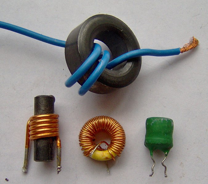
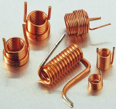
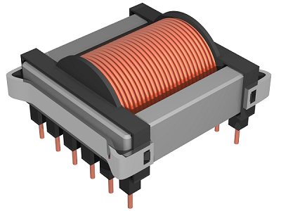
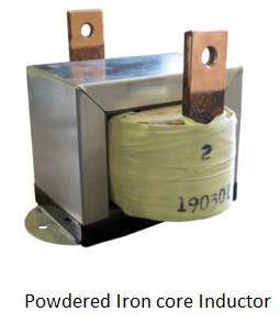
| Variety of inductor forms [1] |
|---|
What are Inductors?
An inductor is a passive component with two terminals, typically constructed of a coil of wire surrounding a "core" of some material, usually a magnetic material like iron or ferrite ceramic, or air (supported by plastic if necessary) [2]. Inductors store electrical energy by inducing a magnetic field when current flows through it, hence the name [2]. Inductors resist change in the current flowing through it by either storing or releasing energy from the magnetic field to create an electromotive force (voltage) to oppose the change; this relationship is described by Lenz's law [2]. This effect is known as inductance [4]. Inductors are useful for many different purposes, including blocking high-frequency noise, electronic filters, tuned circuits, and power converters, any time there might be spikes or changes in current that needs to be controlled [3].
Inductors vs. Capacitors
Inductors are quite similar to capacitors in many respects. For example, they are both two-terminal, passive components, and they both store electrical energy temporarily in some type of field. Inductors and capacitors are useful for this last property, but their main differences are due to which type of field they interact with. Capacitors are said to "resist changes in voltage" while inductors "resist changes in current", which is a result of how capacitors store energy with an electric field, while inductors store energy with a magnetic field [10]. Additionally, capacitors will block direct current from passing through it while inductors will allow it, and vice versa for alternating current [10]. These properties that capacitors and inductors share and differ in mean that they are often used in tandem in the applications mentioned above.
Inductance
Inductance is the ability for an inductor to induce voltage as a result of a change in current, and is denoted with L and measured in Henries (singular Henry, symbol H) [4], though most inductors come in values of microHenry or milliHenry. Inductance is quantified by the ratio of voltage to the rate of change of current [4]. This means that increasing the inductance results in a greater resistance to change, which may be beneficial or detrimental depending on its application. The value of an inductor is influenced mainly by the length of the coil, the cross-sectional area of the coil, the number of turns (of wire), and the magnetic permeability of the core [4]. The length of the coil is inversely proportional to the inductance of the coil, but increasing any of the other three factors will increase the inductance [4].
Inductor Construction
Inductors can be made of a variety of materials. The wire that makes up the inductor coil is usually insulated copper, sometimes aluminum [2]. An ideal inductor would have no resistance, but in the real world, the wire's inherent resistance can become a significant factor due to how much wire goes into making a coil. Like mentioned before, increasing the number of turns in the coil increases the inductance, so the diameter and even cross-section of the wire can be important when many turns are necessary.
The other component is the core, whose shape and material influences the form factor and inductance of the component, which determines what applications the inductor is suitable for.
Contributors:
| User | Last Update |
|---|---|
| Mayurakhi Khan | 1121 days ago |
| Former user (Deleted) | |
| Former user (Deleted) | |
| Former user (Deleted) |
Faculty Advisors: Kim Pope, John Thistle, Allyson Giannikouris, Michael Lenover (alumni)


