Background knowledge
RLS has a good background on different types of encoder which is explained really well. Not worth writing about here because they do such a good job
...
The page on resolution, accuracy and repeatability are particularly important to understand, as these can be the least intuitive to understand (notes below in terms section):
https://www.rls.si/eng/encoder-handbook/resolution-accuracy-repeatability
Type
Terms
Resolution: The smallest movement detected by the encoder
- Measured differently for linear and rotary encoders
Resolution - Linear (μm): The length of one measured step
![]()
Resolution - Absolute Rotary: The number of measured segments/units per revolution
- Ex. 13-bit = 213 = 8,192 steps per rotation
Resolution - Incremental Rotary: Pulses per revolution (PPR) is a signal pulse from one rising edge to the next and Counts per revolution (CPR) marks both rising and falling edges on both channels. You can get the CPR by multiplying the PPR by 4.


Accuracy: how close the output is to where it is suppose to be (where the encoder is saying it should be). It is the max measurement error.
- High resolution does not necessarily mean high accuracy
Repeatability: The max difference between different measurements at the same position.
- Even if all the measurements are wrong, if they are all wrong in the same way (so they are in a similar place at every revolution) it is repeatable.
Types
For our purposes: It has been decided by the other sub-teams to go with absolute rotary encoders for the sake of narrowing the scope of the first revision. In future revisions it might be worth considering to use incremental encoders in addition to the absolute rotary encoders.

Mounting
- Source: https://www.manufacturingtomorrow.com/article/2020/04/best-practices-for-encoder-mounting/15149#:~:text=Encoders%20are%20sensors%20used%20to,%2C%20environmental%2C%20and%20mechanical%20factors.
- Mounting practices depend on the type of encoder
Types of Rotary Encoders
Shafted Rotary Encoders
Required
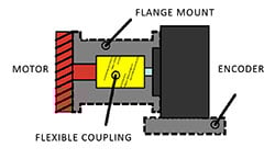
- Encoder Mount - Usually a mounting flange or a foot mount attaching encoder to a fixed surface (typically bracket or adapter)
- Connection from encoder shaft to motor shaft or load - Typically a flexible coupling or a belt drive
- Flexible coupling
- Advantages: Compensates for shaft misalignment, isolates encoder from shock, vibration, noise and movement in the shaft/motor
- Disadvantages: Add space in line with the motor shaft, increases instillation time/complexity
- Flexible coupling

In this example a mounting flange is used (1) and a flexible coupling is used (2)
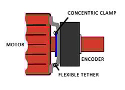
Hollow Shaft Rotary Encoders - Direct Mounting
- Have hollow bores that allow them to be mounted directly on to the shaft of the motor with a concentric clip
- How to install
Required
- Concentric clip - fixes the encoder to the shaft
- Flexible tether or torque arm - Prevents the encoder from rotating with the shaft
In the example a concentric clip is used with a flexible tether to mount a hollow shaft rotary encoder
Hub Shaft Rotary Encoders - Direct Mounting
- Similar to hollow shaft but the encoder caps the end of the shaft
Required
- Plastic sleeve or insert - isolates encoder from motor shaft current (can alternatively use other grounding equipment)
Bearingless Rotary Encoders - Ring or C-Face Mounting
Current Sponsors
For the 2021 season we have full sponsorships from Netzer & RLS
...
If we are sponsored with free sensors we me as well used the best ones available.

Simple Trig & the Tolerance Stackup
...
The zone of tolerance and stackups are shown below qualitatively. It is assumed the joints are stiff and have no play. It is also assumed the link lengths have no error, and the joints are square and concentric.
...
All of the diagrams represent a 2D robot. The gray bars are the links of the arm. of where is should be. The red dots are the point points of each link. The blue dots represent where the arm could be within the accuracy rating of the imaginary encoder on each joint. This is to help better visualize what is important when calculating tolerance stackups. The accuracies are scaled down for visualization
| Linkage | Encoder Accuracy | Diagram |
|---|---|---|
| straight position, equal lengths | 5° each |

| |
| straight position, decreasing lengths | 5° each |


| |
| straight position, increasing lengths | 5° each |


| |
| zig-zag, equal lengths | 5° each |


| |
| Arbitrary angles, equal lengths | 5° each |


| |
| straight position, equal lengths | 1°, 1°, 9°, 9° |


| |
| straight position, equal lengths | 9°, 9°, 1°, 1° |


| |
| straight position, decreasing lengths | 1°, 1°, 9°, 9° |


| |
| straight position, decreasing lengths | 9°, 9°, 1°, 1° |


 | |
| straight position, increasing lengths | 1°, 1°, 9°, 9° |

| |
| straight position, increasing lengths | 9°, 9°, 1°, 1° |


| |
| zig-zag, equal lengths | 1°, 1°, 9°, 9° |


| |
zig-zag, equal lengths | 9°, 9°, 1°, 1° |


| |
| Arbitrary angles, equal lengths | 1°, 1°, 9°, 9° |


| |
| Arbitrary angles, equal lengths | 9°, 9°, 1°, 1° |


|

From this we can draw a few crude conclusions. To get the smallest zone of tolerance at the end effector it is best to stick the most accurate sensors near the root of the arm. It is best to decrease the length of each linkage the farther you go from the root. This will also be true for repeatibility, and backlash of each joint.