Table of Contents
| Table of Contents |
|---|
What is a microcontroller?
A microcontroller is a compact integrated circuit designed to govern a specific operation in an embedded system. It does this by interpreting data it receives from its I/O (Input Output) peripherals using its central processor. The temporary information that the microcontroller receives is stored in its data memory, where the processor accesses it and uses instructions stored in its program memory to decipher and apply the incoming data. It then uses its I/O peripherals to communicate and enact the appropriate action. Microcontrollers are used in multiple industries and applications, including in the home and enterprise, building automation, manufacturing, robotics, automotive, lighting, smart energy, industrial automation, communications and internet of things (IoT) deployments.
Elements of a
Microcontrollermicrocontroller
1: The Processor: A processor can be thought of as the brain of the device. It processes and responds to various instructions that direct the microcontroller's function. This involves performing basic arithmetic, logic and I/O operations. It also performs data transfer operations, which communicate commands to other components in the larger embedded system.
2: Memory : A microcontroller's memory is used to store the data that the processor receives and uses to respond to instructions that it's been programmed to carry out. A microcontroller has two main memory types:
- Program memory, which stores long-term information about the instructions that the CPU carries out. Program memory is non-volatile memory, meaning it holds information over time without needing a power source.
- Data memory, which is required for temporary data storage while the instructions are being executed. Data memory is volatile, meaning the data it holds is temporary and is only maintained if the device is connected to a power source.
3: I/O peripherals : The input and output devices are the interface for the processor to the outside world. The input ports receive information and send it to the processor in the form of binary data. The processor receives that data and sends the necessary instructions to output devices that execute tasks external to the microcontroller.
4: Analog to Digital Converter (ADC) :An ADC is a circuit that converts analog signals to digital signals. It allows the processor at the center of the microcontroller to interface with external analog devices, such as sensors.
5: Digital to Analog Converter (DAC) : A DAC performs the inverse function of an ADC and allows the processor at the center of the microcontroller to communicate its outgoing signals to external analog components.
6: System bus : The system bus is the connective wire that links all components of the microcontroller together.
7: Serial port : The serial port is one example of an I/O port that allows the microcontroller to connect to external components. It has a similar function to a USB or a parallel port but differs in the way it exchanges bits.
| Block Diagram- Microcontroller |
|---|
|

Peripherals and Interfaces
USART (Universal Synchronous/Asynchronous Receiver/Transmitter)
USART is a peripheral that communicates through a serial interface [16]. This means it communicates by sending and receiving each data bit sequentially, or one bit after another. As its name implies, USART can operate in synchronous or asynchronous modes. This Sparkfun article explains concepts needed when trying to understand the differences between the two modes.
When operating asynchronously, the microcontroller’s UART generates a clock and syncs the data stream to that internal clock. Therefore, in the asynchronous mode the receiver only uses the data lines to communicate so the receiver must know what the baud rate is beforehand to interpret the data correctly.
When operating synchronously, the microcontroller’s USART generates a clock, syncs the data stream to that clock, and externally transmits that clock. Therefore, in synchronous mode, an additional clock signal line is needed between the devices in addition to the data lines. This is so the receiver can still interpret the data stream correctly without needing to know the baud rate beforehand by using the clock line. The use of the external clock allows for higher data rates and increases the number of complex protocols the USART peripheral can support. However, UART or USART in asynchronous mode are still more widely used, especially when learning, due to its simplicity and ease of use.
Applications
When developing firmware for embedded systems in IDEs such as MS/AS7, there are no output consoles because the code is run on the microcontroller and not the computer itself. Therefore, a common way for a computer to send commands to and receive feedback from the microcontroller is to use a USB-to-TTL serial converter, bridge, or cable to communicate through a UART serial terminal. In MS/AS7, this Serial Port terminal can be accessed in Data Visualizer. Another popular open-source terminal that can be used is PuTTY.
| Adafruit USB to TTL Serial Cable [17] |
|---|
|

TWI (Two-Wire Interface) /I2C (Inter-Integrated Circuit)
The TWI peripheral provides a bidirectional two-wire interface consisting of one Serial Data Line (SDA) and one Serial Clock Line (SCL) . TWI is almost identical to I2C, also known as I2C, as the TWI name was introduced by some manufacturers, like Atmel, to avoid trademark conflicts with Phillips/NXP’s I2C .
Applications
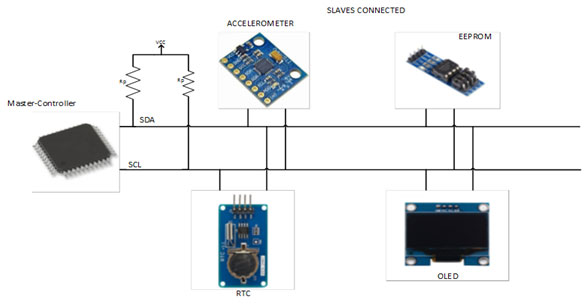
The I2C protocol operates in a master-slave architecture where the master generates the clock signal and the slave is synchronized with the master’s clock. These configurations can include multiple masters and/or multiple slaves. As most MCUs contain TWI peripherals that can operate as a master or a slave, they are often also compatible with most I2C compatible devices such as Real-Time Clocks/Calendars (RTC/C), EEPROMs, sensors, modules, expansion boards, etc.
I2C, and thus TWI, are used for relatively low-speed communications over short to medium distances. As a result, they are only intended for intra-board (between devices on the same PCB) communications, and short inter-board (between devices on different PCBs) communications [21]. This means they can not be used for long PC-MCU connections like with UART.
TWI/I2C are also better suited to connect multiple devices at the same time, up to 128 devices for 7-bit addressing, compared to UART. TWI/I2C are better suited because they have specific features that help with bus contention that the simpler UART does not. These features include clock line synchronization, master/slave addressing, and transmission validation.
Multi-Device I2C Connection Example Diagram [25] |
|---|
|
SPI (Serial Peripheral Interface)
The SPI peripheral communicates through a synchronous serial protocol on a four-wire interface [26]. It consists of a SPI Clock line(SCLK), Master Output/Slave Input line (MOSI), a Master Input/Slave Output line (MISO), and Chip Select line (CS) or sometimes called Slave Select (SS).
SPI operates in a master-slave architecture as a full duplex interface. Similarly to I2C, SPI master devices are the ones that generate the clock signal and SPI slave devices are synchronized to their signal.
Applications
Unlike I2C, SPI is able to operate in full duplex meaning that both a master and slave can transmit data at the same time. This is because the SPI interface has an increased number of wires over UART and I2C. SPI devices also support higher clock frequencies compared to I2C, but only can support one master with multiple slaves.
With higher clock speeds and full duplex communications, SPI generally can handle applications that require faster speeds than I2C. However, SPI is also more susceptible to noise than I2C, so it is better to be used over short distances like in intra-board communications. Therefore, many on-board types of the devices that I2C supports, such as sensors, ADCs, and EEPROM, may also have a version that communicates over SPI instead. Of course, the obvious downside of SPI’s added complexity of two additional wires or pins over I2C may discourage the use of the interface in some designs.
SPI is most often used with devices that require large amounts of data to be transferred quickly like TFT displays, flash memory, and MMC/SD cards.
Multi-Device SPI Connection with Independent Slaves (Left) and Daisy-Chained Slaves (Right) Example Diagram [28] |
|---|
|

Interrupts
When an interrupt fires, the main program stops to execute the code inside its corresponding Interrupt Service Routine (ISR). After the ISR is completed, the program continues from where it was stopped when the interrupt was fired . Therefore, it is important to keep the ISR as short as possible to avoid conflicts with the rest of the program. This can be done by avoiding additional function calls inside the ISR as the ISR would have to wait until that function call is finished before the main program can continue.
An ISR can be implemented like how any other function is called with “ISR” being the function name and the interrupt vector name as the only parameter.
"_vect" must be added to the end of the name of the desired peripheral interrupt source to create the correct name macro for the ISR parameter. In the previous Timer/Counter section, with the Periodic Interrupt example, to create an ISR that is executed whenever Timer/Counter A (TCA0)'s base counter is equal to the value in its Period register, the interrupt vector was created by appending "_vect" to "TCA0_OVF" to create “TCA0_OVF_vect” that was used as the parameter for the ISR.
For some idea of the peripherals that can trigger interrupts, the table below contains all of the interrupt vector mappings for the ATtiny3216/3217.
ATtiny3216/3217 Interrupt Vector Mapping Table 7-2 [18] |
|---|
|

Examples of Microcontrollers
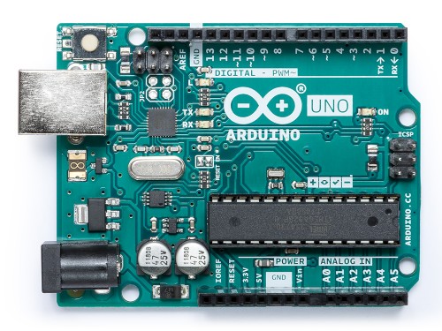
Arduino UNO Rev3
Arduino Uno Rev3 (https://store.arduino.cc/usa/arduino-uno-rev3) is an open-source microcontroller board based on the Microchip ATmega328P microcontroller and developed by the tech company Arduino. The board is equipped with sets of digital and analog input/output (I/O) pins that may be interfaced to various expansion boards (shields) and other circuits. It has 14 digital input/output pins, 6 analog inputs, a 16 MHz quartz crystal, a USB connection, a power jack, an ICSP header and a reset button. Since it has everything required for supporting the microcontroller, one can simply connect it to a computer with a USB cable or power it with a AC-to-DC adapter or battery to get started.
Advantages: Arduino Uno is easy to learn, has low costs, plus a wide array of sensors and several third-party libraries. There’s a large number of (online and free) resources that can be used with this IoT board.
Disadvantages: When compared to Raspberry Pi, Arduino Uno needs some effort in order to carry out tasks such as scheduling and database storage. So Arduino is not a great choice if you need more processing power and memory.
Arduino Uno projects: Arduino Uno is perfect for projects such as programming a temperature and humidity sensor, detecting motion with AC/ static electricity, controlling an automated soldering robotic arm and so on.
BeagleBoard: BeagleBone Black
The BeagleBoard (https://beagleboard.org/black) is a low-power open-source single-board computer produced by Texas Instruments in association with Digi-Key and Newark element14. It runs on Ångström, a Linux distribution and was built by a small team of engineers as an educational board that could be used in colleges around the world to teach open source hardware and software capabilities. In that sense, it is a lot like the Raspberry Pi.
The BeagleBone Black’s features include 512MB DDR3 RAM, 4GB 8-bit eMMC on-board flash storage, 3D graphics accelerator, NEON floating-point accelerator and 2x PRU 32-bit microcontrollers. On the connectivity front, it has USB client for power & communications, a USB host, Ethernet, HDMI and 2x 46 pin headers.
Advantages: The BeagleBoard, especially the BeagleBone Black version, is easy and inexpensive to set up and use. It consumes low power and thus needs no additional cooling or heat sinks. Plus the BeagleBone Black features 65 input and output pins and a huge number of supported interfaces, making it ideal for projects dealing with electronics. Moreover, there’s the PocketBeagle, which provides identical computing performance to BeagleBone Black along with 50 percent reduction in size, 75 percent reduction in weight and 40 percent cheaper purchase price.
Disadvantages: The BeagleBoard is not the best bet for complex multimedia and Linux-based projects as it doesn’t have the graphical and audio capabilities that the Raspberry Pi has.
BeagleBoard projects: BeagleBoard is ideal for beginners in electronics and programming. So projects that require reading from external sensors, commanding actuators (such as motors or light systems), and networking are simpler and more efficient with the BeagleBone Black than with a Raspberry Pi.

Particle Boron
A development board that lets one connect a mesh network to over a cellular service, Particle Boron (https://docs.particle.io/boron/) can act as a standalone cellular endpoint or LTE enabled gateway for Particle Mesh networks. Based on the Nordic nRF52840 SoC (System on a Chip), it has a built-in battery charging circuitry. In other words, it’s a lot like the Electron, except with more features such as mesh networking and Bluetooth. It also boasts two SARA cellular modules, NFC, lots of GPIOs, LiPo charging and more. The board can act as a standalone cellular endpoint or an LTE enabled gateway for a Particle Mesh network. The Boron is also configured in the popular Feather footprint and is thus compatible with Feather Shields. Getting a Boron gives one access to the Device Cloud (10 free micro networks up for grabs) along with three free months of device Cloud access using a cellular gateway.
Advantages: Particle Boron’s big advantage over Particle Electron is that Particle Borons can communicate with each other over WIFI and then pass on the information to a central station which is far away over a cellular network. Moreover, the Boron costs less than the Electron, in addition to offering features such as header pins, LiPo connector, and buttons.
Disadvantages: One big disadvantage of moving from Particle Electron to Particle Boron would be the loss of surface mountability.
Particle Boron projects: The Particle Boron is a good choice as a gateway to link an entire group of local endpoints where Wi-Fi is missing or unreliable; it is also ideal for connecting projects to the Particle Device Cloud.

ESP8266
ESP8266 (https://www.espressif.com/en/products/socs/esp8266) is a low-cost Wi-Fi microchip with full TCP/IP stack and microcontroller capability produced by Shanghai-based Chinese manufacturer Espressif Systems. It contains a built-in 32-bit low-power CPU, ROM and RAM. It is a complete and self-contained Wi-Fi network solution that can carry software applications as a stand-alone device or connected with a microcontroller (MCU). The module comes fitted with an AT Command firmware that can be used with any MCU via COM port. Fitted with a L106 32-bit RISC microprocessor core based on the Tensilica Xtensa Diamond Standard 106Micro running at 80 MHz, it has 16 GPIO pins. On the memory front, it has 32 KiB instruction RAM, 32 KiB instruction cache RAM, 80 KiB user-data RAM and 16 KiB ETS system-data RAM. Other features include WEP or WPA/WPA2 authentication.
Advantages: The advantages of the ESP8266 include its low cost, reliability and easily availability in the market.
Disadvantages: Until a while ago, most of its documentation was in Mandarin, although the emergence of the ESP8266 community in recent days has helped translate several details about programming.
ESP8266 projects: Examples of ideal projects include tracking geolocation, building a wireless web server, putting pressure sensors on railway tracks to detect animal presence and set off an alarm (thus avoiding animal deaths on tracks), building smart plugs, humidity and temperature monitoring, and even making a personal assistant of your own (think along the lines of SIRI, Google Assistant, Alexa!).

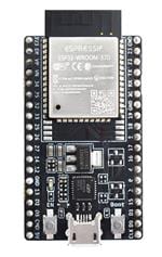
ESP32
A low-cost, low-power system from a chip (SoC) series that has been created by Espressif Systems, ESP32 (https://www.espressif.com/en/products/socs/esp32) comes with Wi-Fi & dual-mode Bluetooth capabilities. One of the key features is its dual-core or single-core Tensilica Xtensa LX6 microprocessor with a clock rate of up to 240 MHz. Highly integrated with built-in antenna switches, RF balun, power amplifier, low-noise receive amplifier, filters, power management modules, touch sensitive pins, built-in hall effect sensor and temperature sensor, ESP32 has been engineered for mobile devices, wearable electronics, and IoT applications.
Advantages: The successor to ESP8266, ESP32 too is rather easy on the pocket. Moreover, it offers ultra-low power consumption thanks to its power saving features such as fine resolution clock gating, multiple power modes, and dynamic power scaling. The ESP32 also has many more GPIOs than the ESP8266.
Disadvantages: Priced at between $6 to $12, the ESP32 costs slightly more than the ESP8266, which costs between $4 to $6.
ESP32 projects: Given its many features, the ESP32 can be used for a slew of DIY (Do It Yourself) IoT projects and DIY smart home projects. Some instances include sensor-based projects such as creating an all-in-one ESP32 weather station shield and working with barometric sensor; data logging projects like recording the temperature to MicroSD card and web-based projects such as setting an ESP32 Access Point (AP) for the web server.
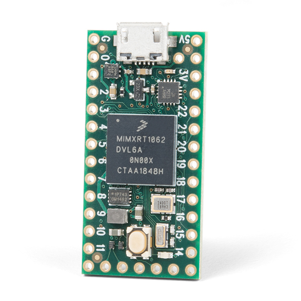
Teensy 4.0
Among the fastest microcontrollers available today, Teensy 4.0 (https://www.sparkfun.com/products/15583) can run at 600 MHz and take up approximately 100 mA current while doing so. Moreover, Teensy 4.0 supports dynamic clock scaling; in fact, Teensy 4.0 can also be overclocked beyond 600 MHz! Unlike typical microcontrollers, where changing the clock speed leads to incorrect baud rates and other issues, Teensy 4.0 hardware and Teensyduino’s software support for Arduino timing functions are built to accommodate dynamically speed changes. So even when the CPU changes speed, serial baud rates, audio streaming sample rates, and Arduino functions like delay() and millis(), and Teensyduino’s extensions like IntervalTimer and elapsedMillis, work well. Teensy 4.0 also has a power shut off feature in that one can connect a pushbutton to the On/Off pin, and completely disable the 3.3V power supply by holding the button for 5 seconds. Teensy 4.0’s RTC (Real Time Clock) functionality can also keep track of date & time while the power is off, provided a coin cell is connected to the voltage of the battery.
Advantages: Speed is certainly one of the main advantages here: testing on real-world examples shows Teensy 4.0 to be capable of executing code more than five times faster than the Teensy 3.6, and fifteen times faster than the Teensy 3.2. Plus it has a posse of peripherals, such as two 480 Mbps USB ports, 3 digital audio interfaces, 3 CAN busses, and multiple serial interfaces.
Disadvantages: The Teensy 4.0 may look similar to the board sharing the same form factor, Teensy 3.2, but it is much better in most aspects. On the price front, it costs $19.95, just a wee bit more than Teensy 3.2 that’s priced at $19.80.
Teensy 4.0 projects: Teensy 4.0 is a good choice for IoT projects such as audio synthesis and analysis. First-time makers can do well by starting off with a board created with beginners in mind and Teensy 4.0 isn’t exactly such a board. But for those who have worked on a few IoT projects already, it’s a no brainer to pick Teensy 4.0 as it offers the horsepower of a Y2K desktop at a price that boards with less than a tenth of this horsepower sell at.
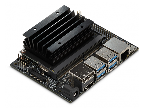
NVIDIA Jetson Nano
A small, powerful computer that lets one run multiple neural networks in parallel for applications like image classification, object detection, segmentation, and speech processing, the NVIDIA Jetson Nano (https://developer.nvidia.com/embedded/jetson-nano-developer-kit) is rather easy-to-use and it takes up as little as 5 watts. This developer kit can be powered by micro-USB and is also supported by NVIDIA JetPack, which includes a board support package (BSP), Linux OS, NVIDIA CUDA®, cuDNN, and TensorRT™ software libraries for deep learning, computer vision, GPU computing, multimedia processing, and much more. The software, on the other hand, is available using an easy-to-flash SD card image, making it easy to get started. The best part is that the same JetPack SDK is used across the entire NVIDIA Jetson family of products and thus allows for full compatible with NVIDIA’s world-leading AI platform for training and deploying AI software. This in turn reduces complexity and work for developers.
Advantages: One of the biggest advantages is that it is an AI computing platform offering GPU-accelerated parallel processing. The Jetson Nano has a 128 CUDA core GPU based on the Maxwell architecture. Also, Nvidia has an open source project called Jetson Inference; it runs on all its Jetson platforms, including the Nano. The Jetson Interference demonstrates various machine learning techniques such as object recognition and object detection. This makes the Nano an ideal starting point for developers looking to build real-world machine learning projects.
Disadvantages: While the hardware is very impressive, better support is needed on software end. Another deterrent is the cost. Priced at $99, it is way more expensive than its rivals such as the Raspberry Pi.
NVIDIA Jetson Nano projects: The Jetson Nano is being used in the development of scores of new small, low-power Artificial Intelligence (AI) systems. It is also popular when it comes to embedded IoT applications, including entry-level Network Video Recorders (NVRs), home robots, and intelligent gateways with full analytics capabilities.
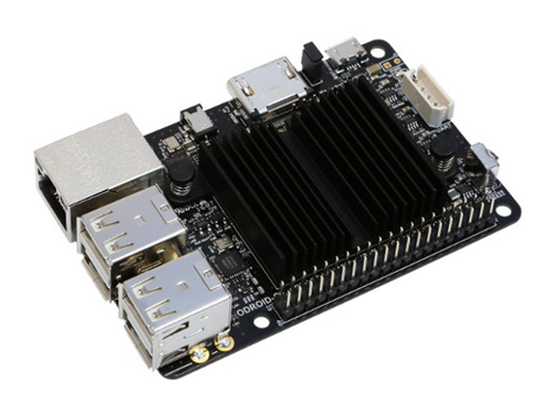
ODROID boards
ODROID (https://www.hardkernel.com/) refers to a series of single-board computers and tablet computers created by the South Korean company, Hardkernel Co, Ltd. The word ODROID is a portmanteau of open + Android, and yet the hardware is not actually open because some parts of the design are retained by the company. Several ODROID systems are capable of running not only Android, but also regular Linux distributions.
The ODROID boards are quite similar to Raspberry Pi, and in many areas, they fare better as well. They typically have a powerful CPU, more RAM and a higher price. For instance, the XU models feature an Exynos SoC even as the C models boast an Amlogic system on a chip (SoC). Both have an ARM CPU and an on chip GPU. While the CPU architectures include ARMv7-A and ARMv8-A, the board memory ranges from 1 GB RAM to 2 GB RAM. Most boards have between three and five mixed USB 2.0 or 3.0 slots, HDMI output, and a 3.5 mm jack. Many of the general-purpose input/output (GPIO) pins offer a lower level output. The latest models have a Gigabit Ethernet (8P8C) port and eMMC module socket. Like with Raspberry Pis, SD cards are used to store the operating system and program memory in the SDHC or MicroSDHC sizes.
Advantages: ODROID boards are typically way faster than Raspberry Pis, especially up to Raspberry Pi 3. Also, the ODROID-C2 comes with a huge heat sink, another big advantage. Another plus is the fact that the ODROID-C2 board layout is almost exactly the same as that of the Pi B+/2/3. So the largest components (think LAN, USB, HDMI, OTG, GPIO and the screw holes for mounting) are similarly placed allowing someone who has the proper mounts/cases for a Pi to easily work with an ODROID-C2 (in most situations anyway).
Disadvantages: In comparison to Raspberry Pi, ODROID boards are more expensive. This makes Raspberry Pis more value for money; for instance the Raspberry Pi 3 has in-built Bluetooth and WIFI. Also, ODROID boards do not enjoy the same quality software and community support that Raspberry Pis do. In fact, it should be acknowledged that the release of Raspberry Pi 4 has only made it tougher for people to opt for ODROID boards.
ONDROID projects: There is a host of projects one can work on with ODROID boards. Right from building digital photo frames and environmental sensors for game machines to putting together an entertainment system and game kits, ODROID boards are useful for many fun projects.
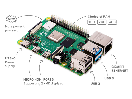
Raspberry Pi 4
The all-new Raspberry Pi 4 Model B (https://www.raspberrypi.org/products/raspberry-pi-4-model-b/) is the latest version of the low-cost Raspberry Pi computer. This credit-card sized electronic board comes with several improvements. For one, it has a USB-C for the power connector and this USB can support an extra 500mA of current, thus offering1.2A for downstream USB devices. The type-A (full-size) HDMI connector has been replaced with a pair of type-D (micro) HDMI connectors; this in turn allows for dual display output within the existing board footprint. The Gigabit Ethernet magjack is now to the top right of the board, instead of the bottom right in Raspberry Pi 3.
In addition to this, the Raspberry Pi 4 boasts an overhauled operating system, based on the forthcoming Debian 10 Buster release. The user interface has been modernized and updated applications include the Chromium 74 web browser. Also, the legacy graphics driver stack used on previous models has given way to the Mesa“V3D” driver which in turn allows for doing away with almost half of the lines of closed-source code in the platform, in addition to offering the ability to run 3D applications in a window under X, OpenGL-accelerated web browsing and desktop composition.
Advantages: As mentioned above, the Raspberry Pi 4 is faster and more capable than its predecessors due to the scores of improvements. It can also play 4K video at 60 frames per second, unlike Raspberry Pi 3. Other Pi 4 features include built-in Wi-Fi and Bluetooth. The latest board is also capable of booting directly from a USB-attached hard drive or pen drive.
Disadvantages: The Raspberry Pi 4 can run Windows 10 but it’s important to keep in mind that it is not anything like the full desktop version of Windows 10; it is but a low cost alternative. Similarly, while it can run Windows desktop apps, it will need a lot of effort to make that happen, and even then apps are more likely to run poorly. It also continues to lack internal storage but one can use SD cards to address this.
Raspberry Pi 4 projects: Like its predecessors, the Raspberry Pi 4 is an incredibly useful IoT board that can be used for numerous projects. Examples include filming one’s own stop motion video, building one’s own Pi web server, a Raspberry Pi home security system, or a Raspberry Pi home automation system, building a virtual jukebox, creating a network monitoring tool, a Raspberry Pi robot and many more.
Rock Pi 4C
The Rock Pi 4C (https://wiki.radxa.com/Rockpi4), priced at $74.95, is a variant of the similarly open-spec Rock Pi 4, a Rockchip RK3399 based SBC by the company Radxa. It’s actually based on the Rock Pi 4B, a $74.95 model with 4GB RAM and a Wi-Fi/Bluetooth module. One of its key features is that it has a mini-DisplayPort which in turn enables dual display support. The full-size HDMI 2.0 port has now been replaced by a micro-HDMI port and the mini-DP is enabled via the hexa-core RK3399 SoC’s USB Type-C controller. This SBC also has a new 64-bit single chip RAM module; in many ways, it is identical to the Rock Pi 4B, which is similar to the Raspberry Pi layout and feature set. It comes with 2x USB 3.0 ports and two USB 2.0 ports.
Advantages: Gamers in particular are being pegged as potential consumers of this SBC as it supports multiple (dual) displays. Rock Pi 4C can also support up to one 4K monitor and one 1440p resolution monitor with both running at 60 Hz.
Disadvantages: The Rock Pi 4C also has some limitations. The micro HDMI port can support up to a 3840 x 2160 pixel, 60 Hz display — while the mini DisplayPort has a max capacity of offering a resolution of 2560 x 1440 pixels, 60 Hz. And while one can use both 1080p or 1440p screens at once, it is important to remember that since Rock Pi 4C’s USB Type-C controller is used to support dual USB 3.0 host ports and the mini DisplayPort, it’s only a 2-lane DisplayPort rather than the usual 4-lanes.
Rock Pi 4C projects: With multiple displays, game enthusiasts are likely to see potential in Rock Pi 4C to build and play games with this SBC. All in all, it is a decent and fairly powerful Raspberry Pi 4 alternative for makers, hobby electronics engineers and PC builders.

UDOO X86 ULTRA (SBC)
The UDOO X86 ULTRA (https://shop.udoo.org/udoo-x86-ii-ultra.html) is a powerful x86 maker board and an Arduino 101-compatible platform, combined to make one board. The resulting board is ten times more powerful than a Raspberry Pi 3 and it can run most applications that one usually runs on a PC on a daily basis plus some 3D games. It supports Linux, Android, and Windows 10. Specs include upto 8GB dual channel RAM, a 2.56 GHz CPU with a 64 bit Quad core processor, three simultaneous screens (one HDMI and two MiniDP++), WiFi and Bluetooth 4.0.
Advantages: It has a huge processing power, way more than most SBCs. Despite the small community, it is quite helpful and has quite a few good guides. UDOO X86 ULTRA is fanless and energy efficient (taking up less than 11 watts at any given time), easy to set up, enjoys decent GPIO support and has great storage; it comes with 32GB eMMC (embedded Multimedia Card, basically a built-in SSD). It also has great wired connectivity and media streaming potential.
Disadvantages: It is quite expensive for an SBC and has poor wireless connectivity. Moreover, demanding games can not be played on the UDOO X86 ULTRA.
UDOO X86 ULTRA projects: You can work on projects such as retrofitting (and thus upcycling) classic electronic items such as a vintage radio for the modern age by running it on Android; creating an ambient light system; or even making an UDOO X86 ULTRA-enhanced guitar - one that has MIDI and FX controls built into it.

Tessel 2 (SBC)
A robust IoT and robotics development platform, Tessel 2 (https://tessel.io/) allows one to tap the libraries of the Node.js web development framework so as to make a variety of useful devices within a short span of time. This primary processor of the Tessel 2 runs a very lightweight version of Linux called OpenWRT.
Advantages: Tessel 2 has WiFi and a bunch of GPIOs and its development environment is built around Javascript, making it a formidable choice.
Built to allow the fastest possible production, its USP is its plug and play modules and high-level APIs are its USP. One doesn’t have to set up and maintain a Linux system or track down pinout diagrams to wire up sensors here. Its specs include a 580MHz WiFi router system on chip, 64 MB of DDR2 RAM, 32 MB of flash storage, two high-speed USB 2.0 ports, a micro USB port, a 10/100 Ethernet port (RJ-45 jack) and a 48MHz ARM Cortex M0 microcontroller.
Disadvantages: The Tessel 2 looks good but it is not as cost efficient as Raspberry Pi nor does it offer enough additional utility over the latter.
Tessel 2 projects: Tessel 2 has two custom “module” ports from where one can add 10-pin modules like accelerometers, climate sensors, Infrared and more. Each module has several instructions and tutorials available online. From sensing to actuation to connecting with other devices, interacting with the physical world has been made really simple with Tessel 2. Ideal projects are those that include detecting ambient light, detecting humidity and temperature in the environment, playing and recording audio, connecting Tessel anywhere with support for mobile internet on a GSM based network and so on.

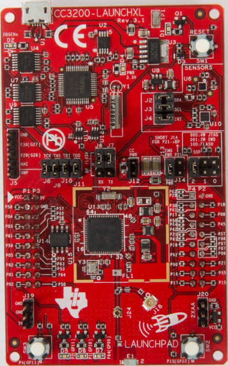
SimpleLink Wi-Fi CC3200 LaunchPad
SimpleLink Wi-Fi CC3200 LaunchPad (https://www.ti.com/tool/CC3200-LAUNCHXL) is a good substitute for Texas Instruments’s entire range of SimpleLink products. Featuring the CC3200 wireless microcontroller (MCU), this is the industry’s first single-chip programmable MCU with built-in Wi-Fi connectivity. It comes with driver support and a software development kit (SDK) with 40 applications for Wi-Fi protocols, internet applications, and MCU peripheral examples.
Advantages: These dev kits can include support for several IoT communication protocols beyond the standard protocols, including more mature protocols like Zigbee and relative newcomers like Thread. Other positives are on-board accelerometers and temperature sensors.
Disadvantages: It has been said that there have been issues sending data to a remote server as the code would always return an error while sending the data.
SimpleLink Wi-Fi CC3200 LaunchPad projects: Its major applications include cloud connectivity, Internet gateway, home automation, industrial control, home appliances, smart plug and metering, access control, wireless audio, security systems, IP network sensor nodes and smart energy.
NanoPi NEO Plus2 (SBC)
An Allwinner based ARM board developed by FriendlyElec, NanoPi NEO Plus2 (http://nanopi.io/nanopi-neo-plus2.html) is rather tiny in that it is less than half the size of the Raspberry Pi. But that doesn’t stop it from offering impressive storage and performance. Its software is Ubuntu Core 16.04, which is a powerful distribution of the Linux OS. It uses Allwinner's 64-bit quad-core A53 SoC with hexa-core Mali450 GPU and also has 1GB DDR3 RAM, 8GB eMMC storage, 10/100/1000M Ethernet based on RTL8211E-VB-CG, WiFi, 4.0 dual mode Bluetooth and 1 MicroSD slot.
Advantages: When compared to the Raspberry Pi, the NanoPi NEO Plus2 comes equipped with gigabit Ethernet with 8 Gbits of eMMC storage and two USB ports. It is has a micro-USB for powering the device and despite being smaller in size, it has expandable memory thanks to its microSD slot. Its other advantages include its relatively low cost, high speed and high-performance computing.
Disadvantages: It does not include an HDMI port and it is nowhere as close as the Raspberry Pi when it comes to assembling a fully functional desktop PC. It also doesn’t have a huge user base and consequently, doesn’t have the support of a community as large as the one that Raspberry Pi enjoys.
NanoPi Neo Plus2 projects: It is ideal for projects involving small IoT appliances, particularly those that need high data throughput, high-speed data transmission and high performance.
NanoPi NEO Plus2 (SBC)

Particle Electron (cellular-enabled IoT board)
Particle Electron (https://docs.particle.io/electron/) is a full-stack IoT device platform with device, connectivity hardware, cloud, and even SIMs for cellular products. This means that when you buy a Particle Electron, you get a cellular module, that allows you to connect with the Internet in over 120 countries, and it is accompanied by a Particle SIM card, a microcontroller, the input and output pins, antenna and USB cable, battery, buttons and LEDs. It has a 120MHz ARM Cortex M3 microcontroller, 1MB flash, 128KB RAM, RGB status LED, 30 mixed-signal GPIO and advanced peripherals plus an open source design.
Advantages: It complies with any cellular standard and comes with 2G/3G connectivity, SIM card, a low-cost data plan, and some great software for making cellular-connected products. Since the Particle Electron is a pre-configured module, it is ready to connect to the internet straight out of the box.
Disadvantages: Cellular connectivity entails license fees and typically, the Particle Electron Iot board is bigger, heavier, more expensive and power consuming than an Iot board that has Bluetooth low energy or Wi-Fi.
Particle Electron projects: The ideal projects include making a GPS + Cellular tracker (to track kids or even valuable objects), monitoring remote sensors and making a high current alarm.

Discovery STMP32MP157C Crypto Board
Just like the Giant Board, the Discovery STMP32MP157C Crypto Board (https://estore.st.com/en/stm32mp157c-dk2-cpn.html) supports embedded Linux development. However, it has a separate 3D graphics processing unit (GPU) that powers the HDMI attached to the LCD display with a touch panel. Also on offer are Ethernet, Wi-Fi, and Bluetooth connectivity.
Advantages: The biggest strength is its STM32MP157 microprocessor. There’s also an audio codec, not to mention the internal M4 MPU that helps with a lower power mode. Overall, its features make it ideal for IoT devices running user-facing applications.
Disadvantages: At almost $100, it is not exactly easy on the pocket.
Discovery STMP32MP157C Crypto Board projects: Given the capabilities of the STM32MP157 microprocessor, this board helps users easily develop applications using STM32 MPU OpenSTLinux Distribution software for the main processor and STM32CubeMP1 software for the co-processor.

Giant Board
The Giant Board (https://groboards.com/giant-board/) is the first-ever single-board computer (SBC) to come in the Adafruit Feather form factor. It comes preloaded with Debian Linux and a Microchip SAMA5D2 ARM® Cortex®-A5 Processor at 500MHz. With MicroSD storage and memory upto 128 MB DDR2 RAM, it also has support for LiPo batteries.
Advantages: It’s quite tiny and is meant to help makers take advantage of Adafruit's Blinka libraries for CircuitPython. Giant Board boasts decent documentation too. It also costs well within $100.
Disadvantages: The Giant Board’s pinout is subject to change.
Giant Board projects: The board is ideal for projects that require a little more power, or a different software stack.

Adafruit FONA (cellular-enabled IoT board)
Adafruit FONA MiniGSM (https://www.adafruit.com/product/1946) is an all-in-one cellular phone module that allows one to add voice, text, SMS and data to one’s project. This board allows one to connect with any global GSM network with a 2G SIM. It also needs a 3-5V microcontroller.
Advantages: With an Adafruit FONA, one can make and receive voice calls from anywhere using a headset, send and receive SMS messages, send and receive GPRS data (TCP/IP, HTTP, etc.) and scan and receive FM radio broadcasts. Other advantages include buzzer vibrational motor control allowing noiseless notifications and AT command interface with “auto baud” detection.
Disadvantages: It needs accessories such as a SIM Card, Lipoly Battery, MicroUSB cable for charging the battery and an external antenna. Also, not all SIM cards may work.
Adafruit FONA projects: Ideal IoT projects are the GPS logging and marking ones as also the geofencing projects that send alerts when the board moves out of a marked area.

References
[1] A. Daga, “AVR Microcontroller : All You Need To Know- (Part 1/46),” Engineers Garage, 01-Jan-2011. [Online]. Available: https://www.engineersgarage.com/article_page/avr-microcontroller-all-you-need-to-know-part-1-46/#:~:text=AVR%20was%20developed%20in%20the,known%20as%20Advanced%20Virtual%20RISC. [Accessed: 04-Feb-2021].
[2] “ATmega328P,” ATmega328P - 8-bit Microcontrollers. [Online]. Available: https://www.microchip.com/wwwproducts/en/ATmega328p. [Accessed: 05-Feb-2021].
[3] “Arduino Uno Rev3,” Arduino Uno Rev3 | Arduino Official Store. [Online]. Available: https://store.arduino.cc/usa/arduino-uno-rev3. [Accessed: 17-Mar-2021]
[4] J. Beningo, “USART vs UART: Know the difference,” EDN, 21-Sep-2015. [Online]. Available: https://www.edn.com/usart-vs-uart-know-the-difference/. [Accessed: 19-Mar-2021].
[5] A. Industries, “USB to TTL Serial Cable - Debug / Console Cable for Raspberry Pi,” Adafruit . [Online]. Available: https://www.adafruit.com/product/954. [Accessed: 19-Mar-2021].
[6] M. Technology, “ATtiny3216/3217 Datasheet,” tinyAVR 1-series, May-2020. [Online]. Available: https://ww1.microchip.com/downloads/en/DeviceDoc/ATtiny3216-17-DataSheet-DS40002205A.pdf. [Accessed: 19-Mar-2021].
[7] “TWI Bus,” I2C Bus, 14-Mar-2016. [Online]. Available: https://www.i2c-bus.org/twi-bus/. [Accessed: 19-Mar-2021].
[8] M. Technology, “ What is TWI? How to Configure the TWI for I2C Communication,” TB3181, 2018. [Online]. Available: http://ww1.microchip.com/downloads/en/DeviceDoc/90003181A.pdf. [Accessed: 19-Mar-2021].
[9] “SparkFun Real Time Clock Module,” BOB-12708 - SparkFun Electronics. [Online]. Available: https://www.sparkfun.com/products/12708. [Accessed: 19-Mar-2021].
[10] “I2C EEPROM - 256k Bit (24LC256),” Sparkfun. [Online]. Available: https://www.sparkfun.com/products/525. [Accessed: 19-Mar-2021].
[11] Yida, “UART vs I2C vs SPI – Communication Protocols and Uses,” Latest Open Tech From Seeed Studio, 16-Nov-2020. [Online]. Available: https://www.seeedstudio.com/blog/2019/09/25/uart-vs-i2c-vs-spi-communication-protocols-and-uses/. [Accessed: 19-Mar-2021].
[12] A. Bhatt, “Understanding the I2C Protocol,” Engineers Garage, 27-May-2020. [Online]. Available: https://www.engineersgarage.com/tutorials/understanding-the-i2c-protocol/. [Accessed: 19-Mar-2021].
[13] P. Dhaker, “Introduction to SPI Interface,” Introduction to SPI Interface | Analog Devices. [Online]. Available: https://www.analog.com/en/analog-dialogue/articles/introduction-to-spi-interface.html. [Accessed: 19-Mar-2021].
[14] A. ON, “Difference between I2C and SPI ( I2C vs SPI ), you should know.,” Aticleworld, 11-Jun-2020. [Online]. Available: https://aticleworld.com/difference-between-i2c-and-spi/#:~:text=I2C%20is%20a%20half%2Dduplex,not%20the%20feature%20of%20SPI. [Accessed: 19-Mar-2021].
[15] “UPDI Physical Interface,” Microchip Atmel-ICE. [Online]. Available: https://onlinedocs.microchip.com/pr/GUID-DDB0017E-84E3-4E77-AAE9-7AC4290E5E8B-en-US-4/index.html?GUID-9B349315-2842-4189-B88C-49F4E1055D7F%C2%A0. [Accessed: 19-Mar-2021].
[16] M. Technology, “AVR Interrupts,” Microchip Developer Help, 19-Mar-2021. [Online]. Available: https://microchipdeveloper.com/8avr:int. [Accessed: 19-Mar-2021].
[17] “Interrupts in AVR MicroController,” javaTpoint. [Online]. Available: https://www.javatpoint.com/interrupts-avr-microcontroller#:~:text=External%20Interrupts%20in%20AVR%20Microcontroller,%22Interrupt%20Sub%2DRoutine%22. [Accessed: 19-Mar-2021].
[18] "We bring you the 10 most popular prototyping and development boards in 2021,” YoungWonks" 19-Mar-2021. [Online]. Available: https://www.youngwonks.com/blog/Top-10-IoT-boards-for-2019. [Accessed: 06-Aug-2021].