Table of Contents
| Table of Contents |
|---|
What is Sensor Interfacing?
Table of Contents
| Table of Contents |
|---|
- Sensor interfacing Interfacing enables a system to read out information from an inputted input signal that is generated by a sensor . This is called and then providing an output signal and it is presented to the user in a way that they can display or it can be process
Interfacing differs per sensor and the type of system that the user is interfacing to
The most common type of systems that are used are:
Microchip PIC microcontrollers
Arduino compatible boards
Raspberry Pi variants
These systems are electronic circuits that can be programmed to carry out a vast array of tasks
PIC
They can be bought as pre-built circuits or as a kit that the user can assemble
They are relatively cheap to buy
To use it, the user needs a computer to run the software on
This software can be Circuit Wizard or Genie Studio, where it allows the user to program the PIC
The microcontroller can come in 8-bit, 16-bit, 32-bit as a MCU(Microcontroller) or a DSC(Digital Signal Controllers)
https://www.microchip.com/design-centers/microcontrollers
The different types of PIC can be found here


How PIC can look like
Arduino
It is an open-source electronics platform
The boards can read inputs and turn them into outputs
For example, it can detect touch through the sensor and then turn the lights one
The user needs to use the Arduino Software (IDE) to program the Arduino to do a set of instructions
Can come in a 8-bit or 16-bit
It runs on a 5 voltage
It stores its memory in a Flash memory, it has 32 KB of memory
- https://www.arduino.cc/en/main/products
- The different types of Arduino can be found in the website link above

Raspberry PI
References
List of Contributors:
contributors- that is easy for the host system to display and process
- Interfacing of sensors usually involves a mix of amplification, filtering and other signal conditioning in order to produce an output signal that the computer would be able to process
- There are two main signals that are used: Analog and Digital
Analog
Analog Signal
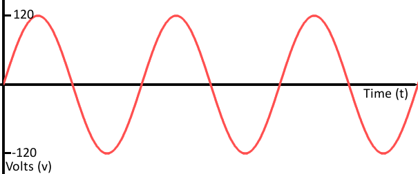
- An analog signal is a continuous signal in which one time-varying quantity (such as voltage, pressure, etc.) represents another time-based variable.
- An analog system allows for a theoretically infinite number of values to be represented
- Video and audio transmissions are often transferred or recorded using analog signals.
- Pure audio signals are also analog.
- The signal that comes out of a microphone is full of analog frequencies and harmonics
Analog Electronics
- Most electronic components are analog (Ex: resistors, capacitors, inductors and diodes)
- Circuits built with a combination of the components are usually analog
- Analog sensors can be complex designs which include many components or they can be vey simple
Analog Signal Graph |
|---|
|
Analog to digital converter (ADC)
ADC's translate analog electrical signals for data processing purposes.
- Converting from analog to digital enables us to use electronics to interface to the analog world.
- In the real world, physical quantities such as temperature, humidity, weight, velocity etc, are analog in nature, ADC's convert these values into a machine readable(digital) format.
- The most common ADC technique uses the analog voltage to charge up an internal capacitor and then measure the time it takes to discharge across an internal resistor. The microcontroller monitors the number of clock cycles that pass before the capacitor is discharged. This number of cycles is the number that is returned once the ADC is complete [1].
ADC Concept |
|---|
|

Digital
Digital Signal
Digital signals must have a finite set of possible values
The set of values can be between two and a large number that is not infinity
Most commonly, the values will be one of the two values
For example, it can be 0V or 5V
Or the digital signal can be discrete representation of an analog waveform
From far away it looks like the line is smooth and analog but when zoomed in there are small discrete steps as the signal tries to approximate the value
Examples of digital signals are HDMI for video (the audio), MIDI, I2S, or AC'97 for the audio
| Digital Signal Changes Between Two Values | When Digital Signal Represents an Analog Waveform |
|---|---|
|
|


Digital Electronics
Digital circuits operate by using digital, discrete signals
These systems are usually made of a combination of transistors, logics gates and at higher levels, microcontrollers, and other computing chips
Most processors whether they are big and found in a computer or tiny microcontroller, they usually operate in the digital realm
Digital circuits usually used binary scheme for digital signaling
These systems assign two different voltages as different logic levels
A high value usually 5V, 3.3V, or 1.8V represent one values
The other low value is usually 0V
Digital circuits are usually easier to design however they can be expensive to build than an analog circuit that would do the same tasks
References
[1]"Analog to Digital Conversion - learn.sparkfun.com", Sparkfun, 2020. [Online]. Available: https://learn.sparkfun.com/tutorials/analog-to-digital-conversion/all#the-analog-world. [Accessed: 15- Dec- 2020].
Contributors:
| Contributors Summary | ||||
|---|---|---|---|---|
|