Table of Contents
| Table of Contents | ||
|---|---|---|
|
| ATtiny 1-Series AVR Microcontrollers [1] |
|---|
|
What are AVR Microcontrollers?
AVR is a family of 8-bit microcontrollers (MCUs) developed by Atmel in 1996, but aquired by Microchip in 2016. Although Atmel has stated that AVR is not an acronym and does not stand for anything, it is commonly accepted AVR is named after its creators, Alf-Egil Bogen and Vegard Wollan RISC, or Advanced Virtual RISC (Reduced Instruction Set Computer) [2] [3]. These AVR MCUs executes most instructions in one clock cycle and therefore consume relatively little power for their speed. This makes them very popular in project prototyping such as in the Arduino UNO and even production embedded systems [4].
Starting in 2016, Microchip has been releasing new generations of ATtiny and ATmega MCUs that have drastically changed how they are programed. These new lines, so far in 2021, are the tinyAVR 0-series,1-series, 2-series and megaAVR 0-series [8]. These new lines share many similarities with the ATxmega line by adding new peripherals, and using new arcitecture, register names, and a programing style that was traditionally reserved for the XMEGA devices [9]. This page will mainly focus on developing firmware for the ATtiny 1-series, specifically the ATtiny3217, in Microchip Studio/Atmel Studio 7 (MS/AS7) with the AVR-GCC Toolchain/Compiler.
Basic Types of AVR Microcontrollers
| Series Name | Images | Pins | Flash Memory (KB) | Characteristics | ||
|---|---|---|---|---|---|---|
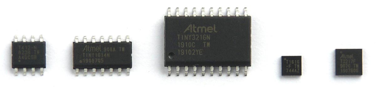
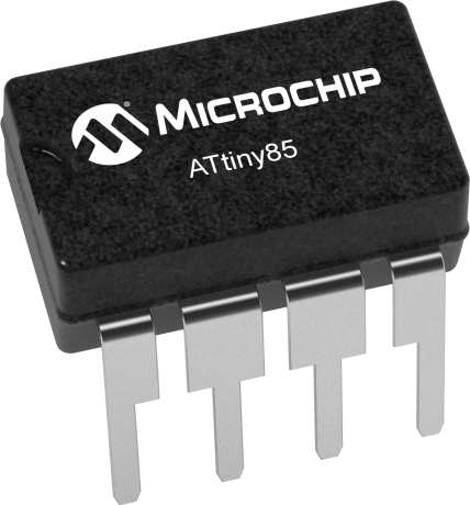
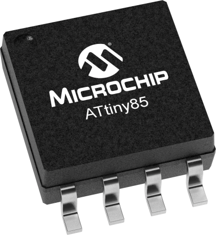
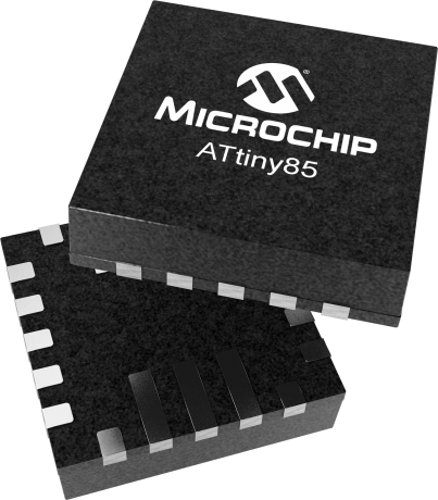
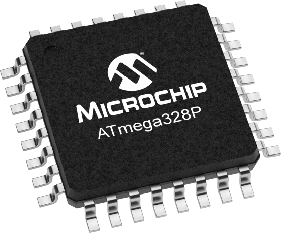
tinyAVR (ATtiny) |
| 6-32 | 0.5 - 32 |
| ||
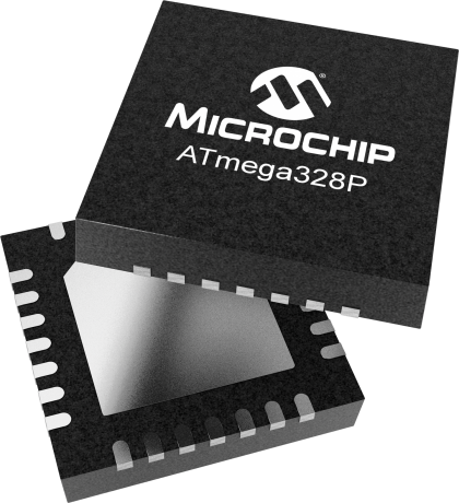
megaAVR (ATmega) |
| 28-100 | 4 - 256 |
| ||
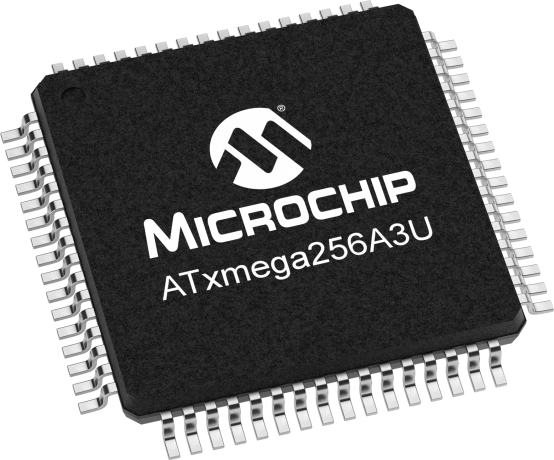
XMEGA (ATxmega) |
| 44-100 | 16 - 384 |
|


tinyAVR 0/1/2-series and megaAVR 0-series Naming Convention [10] |
|---|
|

Getting Started Resources
- AVR MCUs Wikipedia Page
- ATtiny Family Comparison Chart
- AVRFreaks Community Forum
- Getting Started with tinyAVR 1-series
- Tutorials
Programming Languages
The 3 most widely used languages for AVR MCUs are C, Arduino C/C++, and Assembly which is also known as Assembler Language and often abrreviated as ASM [11].
Embedded C (AVR-C)
The newer generations of MCUs improve on accessibilty by adding and renaming registers and macros so that their names more clearly describe its function. This descreases the learning curve for beginners who may not know what all the acryonyms from previous MCU generations mean. This style of programming with registers directly accessed without any operating systems or abstraction layers is reguarly refered to as "bare-metal programming." Datasheets are an extremely useful resource when developing in this style as having to check them continuously for the register architectures and their bit names is an almost certainty.
| Example AVR-C Code Comparision for Simple Blinking LED on PB3 (Port B Pin 3) | |||||||||||||||||||
|---|---|---|---|---|---|---|---|---|---|---|---|---|---|---|---|---|---|---|---|
| ATtiny85 | ATtiny3217 (tinyAvr 1-series) | ||||||||||||||||||
|
| ||||||||||||||||||
The "iotn*.h" file ("iotn3217.h" for ATtiny3217) includes all the macros definitions. A table below also contains common acronyms in macros. This file can be found by higlighting the macro After building the solution at least once, the file can also be found in Solution Explorer > [Your Solution] > [Your Project] > Dependencies | |||||||||||||||||||

Bit Manipulation using Bitwise Operators
| Bitwise Operators Table | ||||||||||||
|---|---|---|---|---|---|---|---|---|---|---|---|---|
| Operator | Definition | Examples | Applications | Application Examples | Notes | |||||||
| & | Bitwise AND: returns 1 for a postion when both binary numbers have 1 at the same postion | 0111 & 1100 = 0100 | Bitwise AND can be used to clear or isolate specific bits in a binary number or register without affecting other bits. |
| When using a ATtiny 0/1/2-series microcontroller, in this specific instance with Port registers, this is not the best way to do this. However, the concept the code demonstrates can be applied to other registers. The best practice would be to use bit masks and the OUTCLR and OUTSET reigsters. An example of this is in the above table. | |||||||
| | | Bitwise OR: returns 1 for a postion when either binary numbers have 1 at the same postion | 0101 | 0110 = 0111 | Bitwise OR can be used to set specific bits in an binary number or register without affecting other bits. |
| When using a ATtiny 0/1/2-series microcontroller, in this specific instance with Port registers, this is not the best way to do this. However, the concept the code demonstrates can be applied to other registers. The best practice would be to use bit masks and the DIRCLR and DIRSET reigsters. An example of this is in the above or below tables. | |||||||
| ^ | Bitwise XOR: returns 1 for a postion when only one of the binary numbers has 1 at the same postion | 1001 ^ 1010 = 0011 | Bitwise XOR can be used to flip or toggle specific bits in an binary number or register without affecting other bits. |
| A common application of this code is to place it in a loop so the Pin can continuously toggle a LED on and off. When using a ATtiny 0/1/2-series microcontroller, in this specific instance with Port registers, this is not the best way to do this. However, the concept the code demonstrates can be applied to other registers. The best practice would be to use bit masks and the OUTTGL reigster. | |||||||
| ~ | Bitwise NOT/ One's Complement: returns the opposite of the value at each postion of the binary number | ~0011 = 1100 | Bitwise NOT can be used to flip all the bits of a binary number. | Bitwise NOT are commonly used with a bit mask and bitwise AND to clear the register's bits that are in the bit mask. An example of this is in the group mask row of the table below. | ||||||||
| << | Bitwise Left Shift: returns the binary number on the left moved left by the number on the right positions | 4-bit Data Type: 1010 << 2 = 1000 8-bit Data Type: 0000 1010 << 2 = 0010 1000 | Bitwise left/right shift can be used to shift a value to the correct postion in a register. | Bitwise left/right shift are commonly used with bit and group postions. An example of this is in the bit and group position rows of the table below. | ||||||||
| >> | Bitwise Right Shift: returns the binary number on the left moved right by the number on the right postions | 4-bit Data Type: 1010 >> 2 = 0010 8-bit Data Type: 1010 0000 >> 2 = 0010 1000 | ||||||||||
| Bit Manipulation Tools' Acronyms Table | |||||||||||||
|---|---|---|---|---|---|---|---|---|---|---|---|---|---|
| Acronym | Definition | Examples | Applications | Application Example | Application Example Explanation | Explanation Notes | |||||||
| bm | Bit Mask: encodes 0b1 at the bit that is used to access the setting or value | 0x04 0b00000100 | A bit mask is often defined for a register where a bit stores a value or controls a setting. A bit mask can be used to access or change the value of a bit. |
| This defines a bit mask macro for Pin 2 and sets Port B's Data Direction Set register to equal it. That then sets the corresponding Pin 2 bit in the Port B's Data Direction register to make Pin 2 an output. | ||||||||
| bp | Bit Position: the location where a bit starts from when counting right to left in a register | 2 | A bit position is often defined for a register where a bit stores a value or controls a setting. A bit position can be used shift a value into the correct bit position in a register. |
| This defines a bit position macro for Pin 1 and bitwise left shifts the value 1 to the Pin 1's bit position. Now with 1 in the correct location, it sets Port B's Data Direction Set register to equal it. That then sets the corresponding Pin 1 bit in the Port B's Data Direction register to make Pin 1 an output. | ||||||||
| gm | Group Mask: encodes 0b1 at each of the bits that is used to access the setting or value | 0x07 0b00000111 | A group position is often defined for a register where multiple bits store a single value or control a single setting. A group mask can be used to access or change the value at multiple bits. |
| This defines a group mask macro for the bits that control ISC. Then "~" flips all of the group mask's bits and bitwise ANDs it with the existing values in Port B's Pin 1 Control register. This clears all the bits that control ISC to 0 while keeping the other bits in the register the same. | ISC stands for Input/Sense Configuration. ISC occupies 3 bits and determines how a port interrupt can be triggered. | |||||||
| gp | Group Position: the location where multiple bits start from when counting right to left in a register | 0 | A group position is often defined for a register where multiple bits store a single value or control a single setting. A group position can be used to shift a value into the correct position of multiple bits in a register. |
| This defines a group position macro for where the bits that control CLKSEL start. It bitwise left shifts the value 0x03 to the bits that control CLKSEL and sets the Clock Controller's Main Clock Control A register equal to it. | CLKSEL stands for Clock Select CLKSEL occupies 2 bits and selects the source for the Main Clock 0x03 is the value for an External Clock source. | |||||||
| gc | Group Configuration: combines a group position and a group mask | (0x03 << 0) | A group configuration is often defined for a register where multiple bits store a single value or control a single setting. A group configuration can be used to set the multiple bits of setting to a predefined configuration. |
| This defines a group configuration macro for an External Clock source by shifting the value that represents it, to the CLKSEL group position. It then sets the Clock Controller's Main Clock Control A register equal to the group configuration macro. | CLKSEL stands for Clock Select CLKSEL occupies 2 bits and selects the source for the Main Clock 0x03 is the value for an External Clock source. | |||||||
Timers/Counters | Getting Started with Timer/CounterA Application Notes
The acronyms for Timer/Counters' names and also used for their respective registers addressing are in the format TCAn [18]. The name starts with "TC'' for Timer/Counter, then a letter corresponding to the Timer/Counter's type, "A" for Timer/Counter type A, then an integer starting from 0 for the Timer instance.
| ATtiny3216/3217 Timer/Counter Definitions Table 20-1 [18] |
|---|
|

In the ATtiny 3216/3217, there are four Timer/Counters in total. There is one 16-bit Timer/Counter type A (TCA0), two 16-bit Timer/Counter type B (TCB0,TCB1), and one 12-bit Timer/Counter type D (TCD0). Timer/Counters of type A (TCA) are the only one that will be explored further as its functions are more often used and the other Timer/Counter types’ functions have many overlapping similarities.
Timer/Counters consist of a base counter and different modes of operations that increment, decrement, clear, and fire interrupts in specific conditions. TCA provides program executing timing, frequency and waveform generation, and command execution. The 16-bit TCA with three compare channels can also be operated in a Split mode to create two 8-bit Timer/Counters with three compare channels each.
| ATtiny3216/3217 TCA Waveform Generation Modes Table 20-6 [18] |
|---|
|

| ATtiny3216/3217 TCA Interrupt Vectors Sources in Normal Mode Table 20-4 [18] |
|---|
|

The clock for TCA that controls the base counter’s ticks can be generated by a pre-scaler and the peripheral clock, or the event system, but the peripheral clock is the more popular choice.
| ATtiny3216/3217 TCA Clock Select Register's Prescaler Table [18] |
|---|
|

Applications
A common basic TCA use case is to trigger an interrupt to run a piece of code periodically. In this case, the Normal operation mode with the overflow interrupt would be likely used. In this configuration, TOP is controlled by the value in the Period register. UPDATE and OVF (Overflow interrupt) is set to be equal to TOP when counting up. Therefore, when the base counter ticks up and is equal to the Period register value, an Overflow interrupt is fired and the base counter is reset to 0.
| Getting Started with TCA Application Notes' Periodic Interrupt Mode Example [34] | |||||||||
|---|---|---|---|---|---|---|---|---|---|
|
Contributors:
| Contributors Summary | ||||
|---|---|---|---|---|
|