Table of Contents
Table of Contents
What is an Operational Amplifier?
An operational amplifier Operational amplifiers (op-amp) are linear devices that are used extensively in signal conditioning, filtering, or to perform mathematical operations such as adding, subtracting, integration, and differentiation. This is due to it having all the properties required for near ideal DC amplification.Fundamentally, it is a voltage amplifying device that is designed to be .
They are used in combination with external feedback components such as resistors, capacitors and inductors between the input and output. The configuration of these components determines the function/operation of the op-amp.
They have a three-terminal device with two high impedance inputs. The input designated by a minus sign (-) is called the "inverting" input, while the other input is designated by a plus sign (+) us called the "non-inverting" input. The third terminal represents the op-amps output which can sink or source either a voltage or current. The output signal is the amplification factor or amplification gain (A) and is multiplied by the input signal. Depending on the nature of the input or output, there are four classifications for op-amp gain [2].
| Input | Output | Classification |
|---|---|---|
| Voltage | Voltage | Voltage |
| Current | Current | Current |
| Voltage | Current | Transconductance |
| Current | Voltage | Trans-resistance |
Figure 1. Operational Amplifier [1] |
|---|
|

Equivalent Circuit
Op-Amp Parameter and Idealized Characteristic
| Parameter | Idealized Characteristic |
|---|---|
| Open Loop Gain (AVO) |
|
Input Impedance (ZIN) |
|
| Output Impedance (ZOUT) |
|
| Bandwidth (BW) |
|
| Offset Voltage (VIO) |
|
The output of the op-amp output is limited by the +Vsupply and the -Vsupply where they are the upper and lower limit of the op-amp respectively [2].
Figure 2. Equivalent Circuit of an Ideal Operational Amplifier [2] |
|---|
|

Basic Configurations
Inverting Op-Amp
This configuration is very simple to implement as it only needs 2 two resistors in its simplest form while having a high level of performance. It consists of a resistor form the input terminal to the inverting input of the op-amp, and another resistor from the output connected to the input. The non-inverting input is grounded.
The main feature of this circuit is the gain that it produces which can be calculated as: [3]
This configuration can be used in summing amplifiers and as a result, has applications in audio mixers and provides low impedance. Another application is that since the output it generates is phase shifted 180 degrees, it can be used as a phase shifter [4].
| Figure 3. Inverting Op-Amp Configuration [3] |
|---|
|

Non-Inverting Op-Amp
This configuration also only requires 2 two resistors in its simplest form. Unlike its inverting counter part, the input signal is simply connected to the non-inverting terminal of the op-amp. The feedback is taken from the output of the op-amp with a resistor to the inverting input of the op-amp with another resistor to ground.
The gain of the circuit can be calculated as:
This configuration is one of the most popular and widely used forms of op-amp circuits. It is primarily used in applications where high input impedance is required [3].
| Figure 4. Non-Inverting Op-Amp Configuration [3] |
|---|
|

Summing Amplifier
This configuration uses the inverting op-amp configuration with the key difference being a series of resistors is added to the virtual ground point at the inverting input. The summing amplifier also known as a linear mixer sums all the signals in a completely linear fashion. The other type of mixer is called a multiplying mixer and uses the non-linear properties of circuits to multiply two signals together and generate additional frequencies.
The output of the circuit can be calculated as:
Where R1x is the value of the resistor at the input. This configuration provides the ideal platform for audio mixing. The various inputs (R1a, R1b, R1c etc.) can be controlled independently as the virtual earth (a node of the circuit maintained at a steady reference potential without being directly connected [5]) of the inverting amplifier is not dependent on the conditions of any of the inputs [3].
| Figure 5. Summing Op-Amp Configuration / Virtual Earth Mixer [4] |
|---|
|

Differential Amplifier
The differential amplifier configuration has an input signal to both the inverting and non-inverting input of the op-amp. This results in the output voltage being proportional to the difference between the two inputs, V1 and V2 . It amplifies the difference between the two voltages making it a subtractor unlike the summing amplifier. Both inputs are connected to ground which allows us to use superposition to solve for the output voltage Vout .
The ideal voltage output of a differential amplifier is:
If all resistors are equal, that is: R1=R2=R3=R4, then the circuit will become a Unity Gain Differential Amplifier and Vout is simply:
The differential amplifier configuration can be used by adding more resistors in parallel with the input resistors to make it either add or subtract voltages applied to the respective inputs. A common method of doing this is to connect a "Resistive Bridge" (Wheatstone Bridge) to the input of the an op-amp [3].
| Figure 6. Differential Op-Amp Configuration [4] |
|---|
|

Integrator Amplifier
In this configuration, by changing the resistive feedback element to a capacitor, we create an RC network across the op-amps feedback path creating an Op-Amp Integrator circuit. This circuit performs integration as the output responds to changes in the input voltage over time since the op-amp produces an output voltage that is proportional to the integral of the input voltage.
The ideal voltage output of an integrator amplifier is:
This can be re-written as:
Where ω = 2πƒ and Vout is a constant 1/RC times the integral of the input voltage VIN with respect to time and is phase shifted 180° as indicated by the negative [4].
The integrator amplifier circuit has many applications. They are most commonly seen in analogueanalog-to-digital converters, ramp generators, and in wave shaping. They also see usage in analogue analog computers to perform calculus operations [6].
| Figure 7. Integrator Op-Amp Configuration [4] |
|---|
|

Differentiator Amplifier
In this configuration compared to the integrator amplifier, the resistor and capacitor have reversed positions and now reactance is connected to the input. This circuit performs differentiation as the voltage output it produces is directly proportional to the input voltage's rate-of-change with respect to time.
The ideal voltage of the differentiator amplifier is:
Thus the output voltage is a constant, -Rf*C times the derivative of the input voltage with a 180° phase shift as indicated by the negative [3].
The differentiator amplifier circuit are most commonly designed to operate on triangular and rectangular signals. They also see usage as wave shaping circuits to detect high frequency components in the input signal [7].
| Figure 8. Differentiator Op-Amp Configuration [4] |
|---|
|

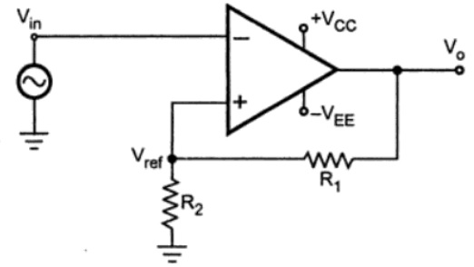
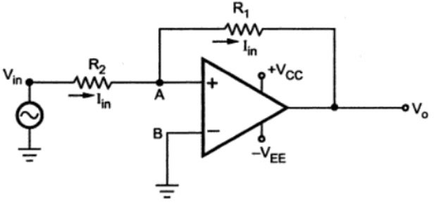
Schmitt Trigger
A Schmitt trigger is a comparator circuit (circuit that compares two voltages and outputs either a 1 or 0 depending on which is larger) that implements hysteresis (the dependence of the state of a system on its history) by applying positive feedback to the non-inverting input of the op-amp. In the non-inverting configuration, when Vin is greater than some chosen threshold as indicated by Vref , then the output is high, or VSAT . If the input becomes less than Vref , the output will become V-SAT . This dual threshold is called hysteresis and allows the Schmitt trigger to be used as a bistable multivibrator (latch or flip-flop). They are very similar to the basic inverting and non-inverting op-amp configurations except that the inputs are switched.
Schmitt triggers are usually used in signal conditioning applications to remove noise from signals in digital circuits, particularly in mechanical contact bounce in switches. Other applications include closed loop negative feedback, relaxation oscillators, function generators and switching power supplies [8].
| Figure 9. Inverting Schmitt Trigger Configuration [8] |
|---|
|
| Figure 10. Non-Inverting Schmitt Trigger Configuration [8] |
|---|
|
Contributors:
| Contributors Summary | ||||
|---|---|---|---|---|
|
Faculty Advisor: Kim Pope, John Thistle, Allyson Giannikouris and Michael Lenover (alumni)