Table of Contents
| Table of Contents | ||
|---|---|---|
|
|
|---|
| ATtiny 1-Series AVR Microcontrollers [1] |
|
What are AVR Microcontrollers?
AVR is a family of 8-bit microcontrollers (MCUs) developed by Atmel in 1996, but aquired by Microchip in 2016. Although Atmel has stated that AVR is not an acronym and does not stand for anything, it is commonly accepted AVR is named after its creators, Alf-Egil Bogen and Vegard Wollan RISC, or Advanced Virtual RISC (Reduced Instruction Set Computer) [2] [3]. These AVR MCUs executes most instructions in one clock cycle and therefore consume relatively little power for their speed. This makes them very popular in project prototyping such as in the Arduino UNO and even production embedded systems [4].
Starting in 2016, Microchip has been releasing new generations of ATtiny and ATmega MCUs that have drastically changed how they are programed. These new lines, so far in 2021, are the tinyAVR 0-series,1-series, 2-series and megaAVR 0-series [8]. These new lines share many similarities with the ATxmega line by adding new peripherals, and using new arcitecture, register names, and a programing style that was traditionally reserved for the XMEGA devices [9]. This page will mainly focus on developing firmware for the ATtiny 1-series, specifically the ATtiny3217, in Microchip Studio/Atmel Studio 7 (MS/AS7) with the AVR-GCC Toolchain/Compiler.
Basic Types of AVR Microcontrollers
| Series Name | Images | Pins | Flash Memory (KB) | Characteristics | ||
|---|---|---|---|---|---|---|
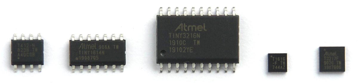
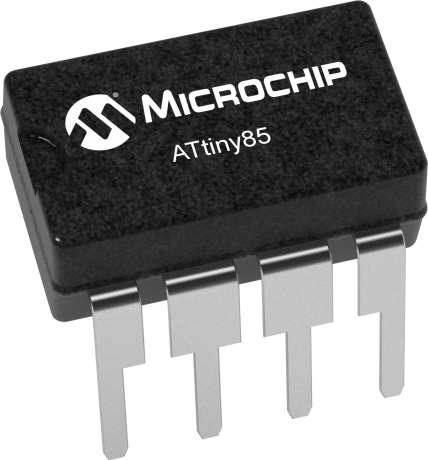
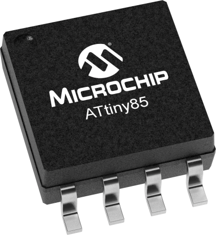
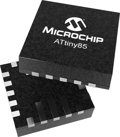
tinyAVR (ATtiny) |
| 6-32 | 0.5 - 32 |
| ||
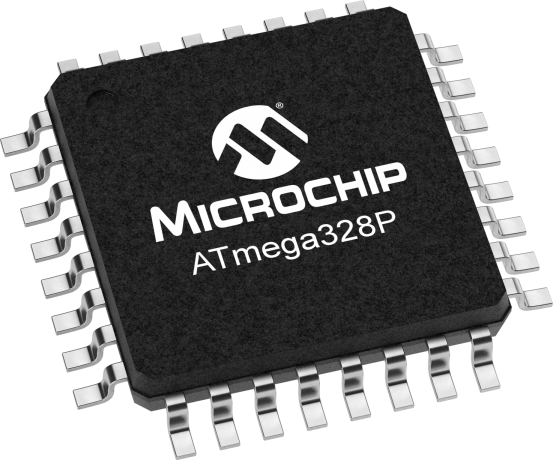
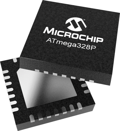
megaAVR (ATmega) |
| 28-100 | 4 - 256 |
| ||
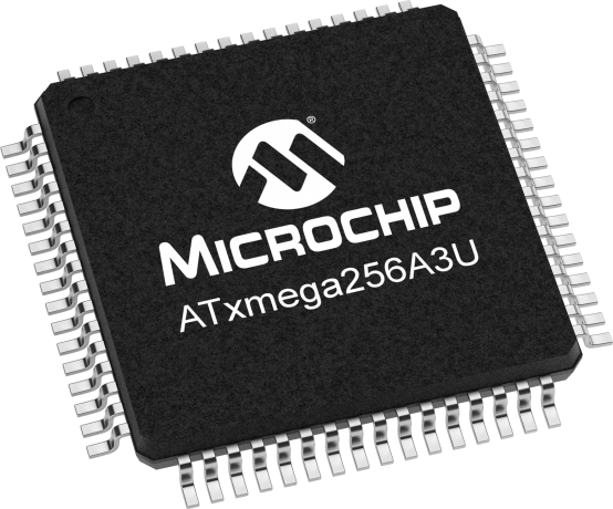
XMEGA (ATxmega) |
| 44-100 | 16 - 384 |
|


|
|---|
tinyAVR 0/1/2-series and megaAVR 0-series Naming Convention [10] |

Getting Started Resources
- AVR MCUs Wikipedia Page
- ATtiny Family Comparison Chart
- AVRFreaks Community Forum
- Getting Started with tinyAVR 1-series
- Tutorials
Programming Languages
The 3 most widely used languages for AVR MCUs are C, Arduino C/C++, and Assembly which is also known as Assembler Language and often abrreviated as ASM [11].
Embedded C (AVR-C)
The newer generations of MCUs improve on accessibilty by adding and renaming registers and macros so that their names more clearly describe its function. This descreases the learning curve for beginners who may not know what all the acryonyms from previous MCU generations mean. This style of programming with registers directly accessed without any operating systems or abstraction layers is reguarly refered to as "bare-metal programming." Datasheets are an extremely useful resource when developing in this style as having to check them continuously for the register architectures and their bit names is an almost certainty.
| Example AVR-C Code Comparision for Simple Blinking LED on PB3 (Port B Pin 3) | |||||||||||||||||||
|---|---|---|---|---|---|---|---|---|---|---|---|---|---|---|---|---|---|---|---|
| ATtiny85 | ATtiny3217 (tinyAvr 1-series) | ||||||||||||||||||
|
| ||||||||||||||||||
The "iotn*.h" file ("iotn3217.h" for ATtiny3217) includes all the macros definitions. A table below also contains common acronyms in macros. This file can be found by higlighting the macro After building the solution at least once, the file can also be found in Solution Explorer > [Your Solution] > [Your Project] > Dependencies | |||||||||||||||||||

Bit Manipulation using Bitwise Operators
| Bitwise Operators Table | ||||||||||||
|---|---|---|---|---|---|---|---|---|---|---|---|---|
| Operator | Definition | Examples | Applications | Application Examples | Notes | |||||||
| & | Bitwise AND: returns 1 for a postion when both binary numbers have 1 at the same postion | 0111 & 1100 = 0100 | Bitwise AND can be used to clear or isolate specific bits in a binary number or register without affecting other bits. |
| When using a ATtiny 0/1/2-series microcontroller, in this specific instance with Port registers, this is not the best way to do this. However, the concept the code demonstrates can be applied to other registers. The best practice would be to use bit masks and the OUTCLR and OUTSET reigsters. An example of this is in the above table. | |||||||
| | | Bitwise OR: returns 1 for a postion when either binary numbers have 1 at the same postion | 0101 | 0110 = 0111 | Bitwise OR can be used to set specific bits in an binary number or register without affecting other bits. |
| When using a ATtiny 0/1/2-series microcontroller, in this specific instance with Port registers, this is not the best way to do this. However, the concept the code demonstrates can be applied to other registers. The best practice would be to use bit masks and the DIRCLR and DIRSET reigsters. An example of this is in the above or below tables. | |||||||
| ^ | Bitwise XOR: returns 1 for a postion when only one of the binary numbers has 1 at the same postion | 1001 ^ 1010 = 0011 | Bitwise XOR can be used to flip or toggle specific bits in an binary number or register without affecting other bits. |
| A common application of this code is to place it in a loop so the Pin can continuously toggle a LED on and off. When using a ATtiny 0/1/2-series microcontroller, in this specific instance with Port registers, this is not the best way to do this. However, the concept the code demonstrates can be applied to other registers. The best practice would be to use bit masks and the OUTTGL reigster. | |||||||
| ~ | Bitwise NOT/ One's Complement: returns the opposite of the value at each postion of the binary number | ~0011 = 1100 | Bitwise NOT can be used to flip all the bits of a binary number. | Bitwise NOT are commonly used with a bit mask and bitwise AND to clear the register's bits that are in the bit mask. An example of this is in the group mask row of the table below. | ||||||||
| << | Bitwise Left Shift: returns the binary number on the left moved left by the number on the right positions | 4-bit Data Type: 1010 << 2 = 1000 8-bit Data Type: 0000 1010 << 2 = 0010 1000 | Bitwise left/right shift can be used to shift a value to the correct postion in a register. | Bitwise left/right shift are commonly used with bit and group postions. An example of this is in the bit and group position rows of the table below. | ||||||||
| >> | Bitwise Right Shift: returns the binary number on the left moved right by the number on the right postions | 4-bit Data Type: 1010 >> 2 = 0010 8-bit Data Type: 1010 0000 >> 2 = 0010 1000 | ||||||||||
| Bit Manipulation Tools' Acronyms Table | |||||||||||||
|---|---|---|---|---|---|---|---|---|---|---|---|---|---|
| Acronym | Definition | Examples | Applications | Application Example | Application Example Explanation | Explanation Notes | |||||||
| bm | Bit Mask: encodes 0b1 at the bit that is used to access the setting or value | 0x04 0b00000100 | A bit mask is often defined for a register where a bit stores a value or controls a setting. A bit mask can be used to access or change the value of a bit. |
| This defines a bit mask macro for Pin 2 and sets Port B's Data Direction Set register to equal it. That then sets the corresponding Pin 2 bit in the Port B's Data Direction register to make Pin 2 an output. | ||||||||
| bp | Bit Position: the location where a bit starts from when counting right to left in a register | 2 | A bit position is often defined for a register where a bit stores a value or controls a setting. A bit position can be used shift a value into the correct bit position in a register. |
| This defines a bit position macro for Pin 1 and bitwise left shifts the value 1 to the Pin 1's bit position. Now with 1 in the correct location, it sets Port B's Data Direction Set register to equal it. That then sets the corresponding Pin 1 bit in the Port B's Data Direction register to make Pin 1 an output. | ||||||||
| gm | Group Mask: encodes 0b1 at each of the bits that is used to access the setting or value | 0x07 0b00000111 | A group position is often defined for a register where multiple bits store a single value or control a single setting. A group mask can be used to access or change the value at multiple bits. |
| This defines a group mask macro for the bits that control ISC. Then "~" flips all of the group mask's bits and bitwise ANDs it with the existing values in Port B's Pin 1 Control register. This clears all the bits that control ISC to 0 while keeping the other bits in the register the same. | ISC stands for Input/Sense Configuration. ISC occupies 3 bits and determines how a port interrupt can be triggered. | |||||||
| gp | Group Position: the location where multiple bits start from when counting right to left in a register | 0 | A group position is often defined for a register where multiple bits store a single value or control a single setting. A group position can be used to shift a value into the correct position of multiple bits in a register. |
| This defines a group position macro for where the bits that control CLKSEL start. It bitwise left shifts the value 0x03 to the bits that control CLKSEL and sets the Clock Controller's Main Clock Control A register equal to it. | CLKSEL stands for Clock Select CLKSEL occupies 2 bits and selects the source for the Main Clock 0x03 is the value for an External Clock source. | |||||||
| gc | Group Configuration: combines a group position and a group mask | (0x03 << 0) | A group configuration is often defined for a register where multiple bits store a single value or control a single setting. A group configuration can be used to set the multiple bits of setting to a predefined configuration. |
| This defines a group configuration macro for an External Clock source by shifting the value that represents it, to the CLKSEL group position. It then sets the Clock Controller's Main Clock Control A register equal to the group configuration macro. | CLKSEL stands for Clock Select CLKSEL occupies 2 bits and selects the source for the Main Clock 0x03 is the value for an External Clock source. | |||||||
Arduino C/C++
Many Arduino boards use Atmel (now Microchip) MCUs with the most notable one being the Atmega328 on the extremly popular Arduino Uno. In effect, the Arduino language is built upon the avr-gcc complier and utilizes many open-source C libraries [12]. As a result, fimware for Arduino boards using AVR MCUs can often also its firmware be devloped with standard AVR-C and the opposite can also be done. With some potential porting, many Arduino libraries can also be used for non-Arduino boards and custom PCBs that use AVR MCUs. In fact, MS/AS7 can import a exsiting Arduino project (sketch) as a C++ project. Although this not reccommend for large or complex Arduino projects, this feature can be very convenient for people who are only familar with Arduino-style C++, but want to transition for greater control, efficiency, optimization, or debugging capabilities of their board.
 |
|---|
| Arduino UNO [13] |
It is important to note that the Arduino devices have the Arduino bootloader installed which allows the Arduino IDE to program (flash) the board over the serial UART port. However, MS/AS7 can not communicate with the Arduino bootloader. Therefore, when writing AVR-C code for Arduino devices in MS/AS7, it is recommended to use a external programmer/debugger to flash the board.
|
|---|
| Atmel-ICE Programmer/Debugger [14] |

Arduino Cores
Arduino Cores provide the hardware abstraction layer definitions for the Arduino IDE to access built-in Arduino-style functions like pinMode(), digitalWrite() and Serial.begin() [15]. Therefore, to develop firmware for unsupported boards or MCUs in the Arduino IDE, a new Core specific to their architecture must be installed so that the built-in functions work correctly. These cores are usually open-sourced and created by community members. For example, to develop firmware for the tinyAVR 0/1-series MCUs in the Arduino IDE, Spence Konde's megaTinyCore on GitHub can be installed.
Peripherals and Interfaces
USART (Universal Synchronous/Asynchronous Receiver/Transmitter) | Getting Started with USART Aplication Notes
USART is a peripheral that communicates through a serial interface [16]. This means it communicates by sending and receiving each data bit sequentially, or one bit after another. As its name implies, USART can operate in synchronous or asynchronous modes. This Sparkfun article explains concepts needed when trying to understand the differences between the two modes.
When operating asynchronously, the microcontroller’s UART generates a clock and syncs the data stream to that internal clock. Therefore, in the asynchronous mode the receiver only uses the data lines to communicate so the receiver must know what the baud rate is beforehand to interpret the data correctly.
When operating synchronously, the microcontroller’s USART generates a clock, syncs the data stream to that clock, and externally transmits that clock. Therefore, in synchronous mode, an additional clock signal line is needed between the devices in addition to the data lines. This is so the receiver can still interpret the data stream correctly without needing to know the baud rate beforehand by using the clock line. The use of the external clock allows for higher data rates and increases the number of complex protocols the USART peripheral can support. However, UART or USART in asynchronous mode are still more widely used, especially when learning, due to its simplicity and ease of use.
Applications
When developing firmware for embedded systems in IDEs such as MS/AS7, there are no output consoles because the code is run on the microcontroller and not the computer itself. Therefore, a common way for a computer to send commands to and receive feedback from the microcontroller is to use a USB-to-TTL serial converter, bridge, or cable to communicate through a UART serial terminal. In MS/AS7, this Serial Port terminal can be accessed in Data Visualizer. Another popular open-source terminal that can be used is PuTTY.
|
|---|
| Adafruit USB to TTL Serial Cable [17] |

TWI (Two-Wire Interface) /I2C (Inter-Integrated Circuit) | TWI as I2C Master Application Notes
The TWI peripheral provides a bidirectional two-wire interface consisting of one Serial Data Line (SDA) and one Serial Clock Line (SCL) [18]. TWI is almost identical to I2C, also known as I2C, as the TWI name was introduced by some manufacturers, like Atmel, to avoid trademark conflicts with Phillips/NXP’s I2C [19].
Applications
The I2C protocol operates in a master-slave architecture where the master generates the clock signal and the slave is synchronized with the master’s clock. These configurations can include multiple masters and/or multiple slaves. As most MCUs contain TWI peripherals that can operate as a master or a slave, they are often also compatible with most I2C compatible devices such as Real-Time Clocks/Calendars (RTC/C), EEPROMs, sensors, modules, expansion boards, etc [20].
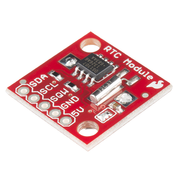 |  |  |
|---|---|---|
| SparkFun DS1307 RTC Module [21] | SparkFun 24LC256 EEPROM IC [22] | Adafruit SHT31-D Temperature & Humidity Sensor [23] |
I2C, and thus TWI, are used for relatively low-speed communications over short to medium distances. As a result, they are only intended for intra-board (between devices on the same PCB) communications, and short inter-board (between devices on different PCBs) communications [21]. This means they can not be used for long PC-MCU connections like with UART.
TWI/I2C are also better suited to connect multiple devices at the same time, up to 128 devices for 7-bit addressing, compared to UART. TWI/I2C are better suited because they have specific features that help with bus contention that the simpler UART does not. These features include clock line synchronization, master/slave addressing, and transmission validation.
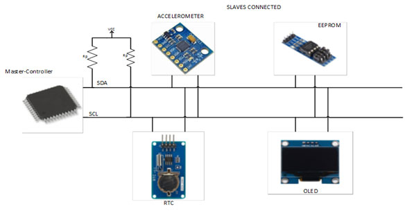
|
|---|
| Multi-Device I2C Connection Example Diagram [25] |
SPI (Serial Peripheral Interface) | Getting Started with SPI Application Notes
The SPI peripheral communicates through a synchronous serial protocol on a four-wire interface [26]. It consists of a SPI Clock line(SCLK), Master Output/Slave Input line (MOSI), a Master Input/Slave Output line (MISO), and Chip Select line (CS) or sometimes called Slave Select (SS).
SPI operates in a master-slave architecture as a full duplex interface. Similarly to I2C, SPI master devices are the ones that generate the clock signal and SPI slave devices are synchronized to their signal.
Applications
Unlike I2C, SPI is able to operate in full duplex meaning that both a master and slave can transmit data at the same time. This is because the SPI interface has an increased number of wires over UART and I2C. SPI devices also support higher clock frequencies compared to I2C, but only can support one master with multiple slaves [27].
 |
|---|
| Multi-Device SPI Connection with Independent Slaves (Left) and Daisy-Chained Slaves (Right) Example Diagram [28] |
With higher clock speeds and full duplex communications, SPI generally can handle applications that require faster speeds than I2C. However, SPI is also more susceptible to noise than I2C, so it is better to be used over short distances like in intra-board communications. Therefore, many on-board types of the devices that I2C supports, such as sensors, ADCs, and EEPROM, may also have a version that communicates over SPI instead. Of course, the obvious downside of SPI’s added complexity of two additional wires or pins over I2C may discourage the use of the interface in some designs.
SPI is most often used with devices that require large amounts of data to be transferred quickly like TFT displays, flash memory, and MMC/SD cards.
 |  |
|---|---|
| Adafruit MicroSD Card Breakout Board [29] | Adafruit Color TFT LCD Display Breakout Board [30] |
UPDI (Unified Program and Debug Interface)
UPDI is a UART-based half-duplex one-wire interface for data reception and transmission [31]. Microchip introduced this new interface standard for the new tinyAVR 0/1-series and megaAVR 0-series generations [32].
Applications
After Microchip acquired Atmel, they developed UPDI as a proprietary interface for external programming and on-chip debugging developed to replace older programming interfaces [31], [33]. The article [33] also explains some of the differences between UPDI and older programming interfaces like ISP and JTAG.
The aforementioned Microchip’s Atmel-ICE is a commercially currently available, as of 2021-03-18, programmer and debugger that supports UPDI as well as JTAG, PDI, SPI, TPI, SWD, aWire, and debugWire [14]. There are also many online DIY tutorials for making a UPDI programmer using an Arduino or another AVR MCU.
Timers/Counters | Getting Started with Timer/CounterA Application Notes
The acronyms for Timer/Counters' names and also used for their respective registers addressing are in the format TCAn [18]. The name starts with "TC'' for Timer/Counter, then a letter corresponding to the Timer/Counter's type, "A" for Timer/Counter type A, then an integer starting from 0 for the Timer instance.
 |
|---|
| ATtiny3216/3217 Timer/Counter Definitions Table 20-1 [18] |
In the ATtiny 3216/3217, there are four Timer/Counters in total. There is one 16-bit Timer/Counter type A (TCA0), two 16-bit Timer/Counter type B (TCB0,TCB1), and one 12-bit Timer/Counter type D (TCD0). Timer/Counters of type A (TCA) are the only one that will be explored further as its functions are more often used and the other Timer/Counter types’ functions have many overlapping similarities.
Timer/Counters consist of a base counter and different modes of operations that increment, decrement, clear, and fire interrupts in specific conditions. TCA provides program executing timing, frequency and waveform generation, and command execution. The 16-bit TCA with three compare channels can also be operated in a Split mode to create two 8-bit Timer/Counters with three compare channels each.
 |
|---|
| ATtiny3216/3217 TCA Waveform Generation Modes Table 20-6 [18] |
 |
|---|
| ATtiny3216/3217 TCA Interrupt Vectors Sources in Normal Mode Table 20-4 [18] |
The clock for TCA that controls the base counter’s ticks can be generated by a pre-scaler and the peripheral clock, or the event system, but the peripheral clock is the more popular choice.
 |
|---|
| ATtiny3216/3217 TCA Clock Select Register's Prescaler Table [18] |
Applications
A common basic TCA use case is to trigger an interrupt to run a piece of code periodically. In this case, the Normal operation mode with the overflow interrupt would be likely used. In this configuration, TOP is controlled by the value in the Period register. UPDATE and OVF (Overflow interrupt) is set to be equal to TOP when counting up. Therefore, when the base counter ticks up and is equal to the Period register value, an Overflow interrupt is fired and the base counter is reset to 0.
| |||||||||
|---|---|---|---|---|---|---|---|---|---|
| Getting Started with TCA Application Notes' Periodic Interrupt Mode Example [34] |
Interrupts | Interrupt System Application Notes
When an interrupt fires, the main program stops to execute the code inside its corresponding Interrupt Service Routine (ISR). After the ISR is completed, the program continues from where it was stopped when the interrupt was fired [35]. Therefore, it is important to keep the ISR as short as possible to avoid conflicts with the rest of the program. This can be done by avoiding additional function calls inside the ISR as the ISR would have to wait until that function call is finished before the main program can continue.
An ISR can be implemented like how any other function is called with “ISR” being the function name and the interrupt vector name as the only parameter [36].
|
|---|
"_vect" must be added to the end of the name of the desired peripheral interrupt source to create the correct name macro for the ISR parameter. In the previous Timer/Counter section, with the Periodic Interrupt example, to create an ISR that is executed whenever Timer/Counter A (TCA0)'s base counter is equal to the value in its Period register, the interrupt vector was created by appending "_vect" to "TCA0_OVF" to create “TCA0_OVF_vect” that was used as the parameter for the ISR.
For some idea of the peripherals that can trigger interrupts, the table below contains all of the interrupt vector mappings for the ATtiny3216/3217.
|
|---|
ATtiny3216/3217 Interrupt Vector Mapping Table 7-2 [18] |

Contributors:
| Contributors Summary | ||||
|---|---|---|---|---|
|