Table of Contents
| Table of Contents |
|---|
Information on connection types specific to valves can be found on the Connection Types - Valves page.
Information on connection types specific to pipes can be found on the Connection Types - Pipes page.
Welded Connections
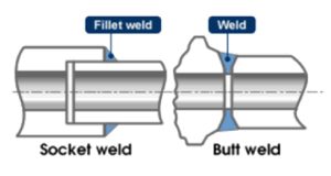
In this connection, the pipes, tubing and/or valves are directly welded together to create a tighter and leak-free joint (in the case of pipes and valves) [1]. There are two types main types of welded connections, the butt weld and socket weld. In a butt weld, the pipe ends/ pipe, valve ends are butted to each other and welded together to form a link [1]. In a socket weld, the end of one pipe is inserted into the socket of another pipe/valve which are then welded together using fillet welds. Socket welds are used with small valves no larger than 2 inches [1].
Further information about weldments can be found on the Weldments page.
Socket Weld vs. Butt Weld [2] |
|---|
| Advantages | Disadvantages |
|---|---|
|
|
Flange Connections
A flange is a protruding ridge or rim, typically used to increase the strength or spread the load of various objects. Objects that often have, or may be fitted with flanges include nuts, bolts, beams and pipes [1]. Pipe flanges have a radially protruding rim with several holes allowing two pipes to be bolted together to form a connection [1]. A gasket may be fitted between the two flanges to improve the seal (Further information about gaskets can be found on the Seals page). Flanges are a a reliable way to connect pipe systems with other equipment and are quick and easy to assemble or repair, making them a popular connection type. The types of flanges include welding neck, slip on, socket weld, lap joint, threaded and blind flange as described below.
To browse an organized list of flange styles, please visit: McMaster-Carr Flanges Catalog [4].
| Flange Type | Image [5] | Description |
|---|---|---|
| Threaded Flange (Screwed Flange) | This style has a thread inside the flange bore which fits a matching thread on the end of a pipe or fitting [5]. In most cases, this threaded connection does not require welding [5]. | |
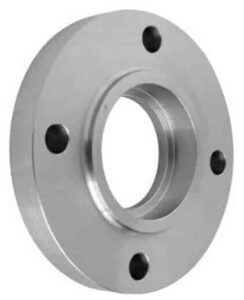
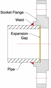
| Socket-Weld Flanges |
| Socket-weld flanges are ideal for pipes with smaller diameters, with low-temperature, low-pressure scenarios [5]. They feature a connection slot into which the pipe can be placed before being secured by a single multi-pass weld [5]. This type is simple to install and avoids the limitations of a threaded connection. |
| Slip-on Flange | Slip-on flanges are of the more common flange connections and come in a wide assortment of sizes to accommodate systems of variable flow rates [5]. To secure the pipe-flange connection, both sides must be fillet welded [5]. | |
| Lap Joint Flange | Lap joint flanges feature a two-piece design, requiring butt welding between the stub end of the flange to the pipe or fitting with a backing flange to form the flanged connection [5]. This style is popular for systems with limited space or which require frequent dismantling/maintenance [5]. | |
| Weld Neck Flange | Similarly to lap joint flanges, weld neck flanges require a butt weld connection. Weld neck flanges a leading choice for process piping due to their integrity in systems with multiple repeat bends, and ability to be used in high-temperature, high-pressure systems [5]. | |
| Blind Flange | Blind flanges are used for terminating or isolating piping systems, as they are essentially bolt-able, solid discs [5]. When installed with the appropriate gaskets, they can provide an excellent seal [5]. Additionally, they are easy to remove when needed. |
| Advantages | Disadvantages |
|---|---|
|
|
Threaded Connections
For information about thread classes, please see the Thread Classes page.
Bevel Seat
Bevel Seat is a connection thread type that is very common in North America. It functions by having a male and female connector be joined together by a gasket, and tightened with a nut to seal [7].
ACME Standards
- Required special tooling wrench to tighten/loosen
- Will leak before failure
- Common thread type in Canada and the US
Bevel Seat Connection [8] |
|---|
DIN
DIN is a threaded connector type first developed in Germany, and stands for Deutsche Industrial Norme. Like the Bevel Seat, it functions with a male and female connector, accompanied by a gasket and a nut to seal. The product however is more common in Europe and China [7].
- Used in food and beverage
- Type 11850: Metric Standard
- Type 11851: Imperial Standard
- Required special tooling wrench to tighten/loosen
- For German brewing, use metric standard DIN Type 11850
- For North American piping, use imperial standard DIN Type 11851
- Will leak before failure
- Used in food and beverage
DIN Connection [9] |
|---|
SMS
A threaded connection type that is less common than DIN. But also functions with a male and female connector, accompanied by a gasket and a nut to seal. Originally developed in Sweden, SMS stands for Swedish Milk Standard [7].
- Required special tooling wrench to tighten/loosen
- Common thread type in Europe and China
- Will leak before failure
SMS Connection [10] |
|---|
NPT Thread
NPT Thread North American technical standard which stands for National Pipe Thread. It functions with a male end and a female end, and is more commonly used for non-sanitary piping rather than sanitary tubing [7].
- Material type requires different sealing aid
- Fluid type requires different sealing aid
- Requires a wrench to install or adjust
- Can be permanent or temporary
NPT Thread Connection [11] |
|---|
| Advantages | Disadvantages |
|---|---|
|
|
Compression Fitting
A compression fitting tightens down a sleeve over a joint to prevent leakage. These connection types are generally very strong and are particularly useful for their temperature and pressure capabilities [13]. The assembly may vary from manufacturer to manufacturer, but they all comprise of three basic elements: a compression nut, one or more ferrules, and a compression fitting body [13]. The tubing is inserted into the end of the fitting and the nut is tightened, forcing the ferrules(s) into the fitting body. As the ferrules move axially into the fitting body, the body will compress the end of the ferrule onto the outer diameter of the tubing, creating a leak tight seal [13].
To browse an assortment of compression fittings, please visit: Swagelock Compression Fittings Catalog [14].
Compression Fitting |
|---|
Exploded View [15] |
|---|
| Advantages | Disadvantages |
|---|---|
|
|
Contributors:
| Contributors Summary | ||||
|---|---|---|---|---|
|
Faculty Advisor: Rachel Malevich (Alumni)


