Table of Contents
| Table of Contents | ||
|---|---|---|
|
What is GD&T?
GD&T, an acronym for "Geometric Dimensioning and Tolerancing", is an international system of symbols used to improve communication throughout the design process [1]. Manufactured products differ from original designs or CAD models, since they cannot be perfectly accurate to dimensions. To account for this, and to save time and money in the fabrication process, engineers use GD&T to clearly represent design intentions on a drawing [2]. There are 14 different symbols, which each relate to geometric characteristics, that comprise GD&T. The symbols can be divided into 5 types of tolerances: Form, Profile, Orientation, Location, and Runout [3]. All GD&T information is stored in a feature control frame. Much of the information on this page was gathered from GD&T Basics, so be sure to visit the website for more detailed information.
GD&T Standard
The most commonly used GD&T standard in Canada, and the one that this page relates to, is the ASME Y14.5 GD&T Standard [27]. The website describes the Y14.5 standard as "the authoritative guideline for the design language of geometric dimensioning and tolerancing (GD&T.) It establishes symbols, rules, definitions, requirements, defaults, and recommended practices for stating and interpreting GD&T and related requirements for use on engineering drawings, models defined in digital data files, and in related documents" [28].
Feature Control Frame
A feature control frame is used on a design drawing to describe the conditions and tolerances that pertain to the tolerance symbol used. The control frame generally consists of 4 parts: a geometric tolerance symbol, tolerance zone type (such as diameter) and value, tolerance modifier, and datum references [4]. This is subject to change, as not all of these are always necessary (or sufficient), and it is common for control frames to contain several sets of symbols [1].
| GD&T feature control frame labelled [5] |
|

Datums
A datum is a virtual reference or anchor location for a part to be dimensioned from. Datums have a symbol which contains a letter, and can be used for profile, orientation, location, and runout tolerances. They can take the form of a point, axis, or plane. A datum feature (not the same as a datum) is the feature of a part that is in contact with the datum, such as an uneven surface [6]. A part can have a primary, secondary, and tertiary datum and should be selected in order of usefulness/importance. Once the primary datum (A) is selected, the secondary (B) must be perpendicular to it, and the tertiary (C) must be perpendicular to the other two [1].
| The datum symbol and corresponding feature control frame [6] |
|

Datum planes can be very effective when working with a part with an uneven surface because dimensions can be taken from the plane, as opposed to the inconsistent surface of the part [1].
| An example of using a datum plane to dimension an uneven part [6] |
|

MMC and LMC Material Conditions
In GD&T, a designer specifies dimensions and a range of tolerances. The difference of value between Maximum Material Condition (MMC) and Least Material Condition (LMC) on a dimension is usually equal to the range of tolerance the designer specifies. Parts weigh the most at MMC and weigh the least at LMC. Thus, a shaft would be at MMC when its diameter is largest, while a hole would be at MMC when its diameter is smallest. A shaft would be at LMC when its diameter is smallest, while a hole would be at LMC when its diameter is largest [1].
| Acronym | Name | Symbol [7][8] | Shaft | Hole |
|---|---|---|---|---|
| MMC | Maximum Material Condition |
|
|
|
| LMC | Least Material Condition |
|
|
|
Geometric Characteristics and Symbols
All symbols except those under the Form tolerance type are measured with respect to a datum.
| Symbols included in GD&T [3] |
|

Form Tolerances
Straightness
The straightness tolerance can refer to surface straightness or center axis/plane straightness on a feature. The part of the drawing that the feature control frame points to indicates what type of straightness is being toleranced [1][9].
| Type | Feature | Feature Control Frame Location | Definition |
|---|---|---|---|
| Surface Straightness | Either | Points to outer edge of the feature | The surface line must lie between two parallel lines. The number in the feature control frame represents the distance between the two lines [9]. |
| Axis Straightness | Shaft | Attached to the diameter dimension callout | The midpoint axis of the part must lie within a cylindrical boundary, which is centered at the theoretical central axis of the part. The number in the feature control frame represents the diameter of the cylindrical boundary [9]. |
| Plane Straightness | Flat Object | Attached to height/width/length dimension callout | The midpoint plane of the part must lie within two parallel planes, which are centred at the theoretical central plane of the part. The number in the feature control frame represents the distance between the two parallel planes [1]. |
| Surface straightness tolerance example [9] | Axis straightness tolerance example [9] |
|  |

Flatness
Flatness describes how flat a surface is regardless of datums or features [10]. The flatness tolerance refers to two parallel planes that are parallel to the considered surface and such surface must lie within these two planes [1]. The tolerance value found in the feature control frame is the tolerance zone, and is the distance between the two parallel planes. All points along the considered surface must lie within this tolerance zone [10].
| Flatness Tolerance Example [10] |
|

Circularity
Circularity compares a circular element of a part to a perfect circle [1]. As long as the element fits within LMC and MMC, it is within tolerance. The number in the feature control frame is the tolerance zone, and it represents the difference in diameter between LMC and MMC.
| Circularity tolerance example [11] |
|

Cylindricity
Cylindricity is a 3D tolerance that compares a cylindrical element to a true cylinder [12]. It focuses on the straightness, roundness and taper of the cylinder in reference [1]. This tolerance refers to two perfect cylinders that run the length of the cylindrical element. One cylinder acts as the inner cylinder and the other is the outer cylinder. All points on the surface of the cylinder element must lie inside the zone created by these two perfect cylinders. The number found in the feature control zone is the tolerance zone and is the distance between the two perfect cylinders [12].
| Cylindricity Tolerance Example [12] |
|

Profile Tolerances
Profile of a Line
The profile of a line tolerance describes a tolerance zone around any curve or line in any feature [13]. It takes a cross-section at any point along a surface and creates a tolerance zone above and below the line. The tolerance zone is made up of two parallel lines that follow the contour of the surface [13]. The tolerance value refers to the distance between the two parallel lines and the profile of this line/curve must remain inside this zone. This tolerance may or may not reference a Datum. This tolerance is commonly used for advanced curved surfaces that curve at multiple axes at once. A specific reference of where it is used is the curvature of an airplane wing as each cross-section on the wing would need to have a different curve profile.
| Example of the Profile of a Line Tolerance [13] |
|

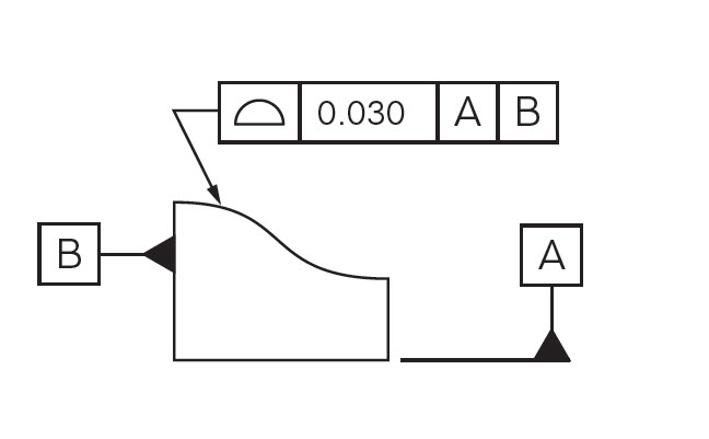
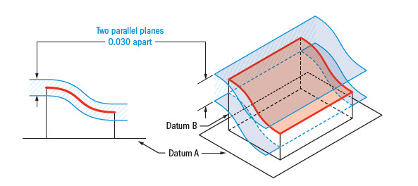
Profile of a Surface
The profile of a surface tolerance is the 3D version of the profile of a line tolerance. It describes a tolerance zone around a curved surface in any feature. The surface must lie between two 3D, parallel surface curves that follow the contour of the surface profile across the entire length of the surface. The tolerance value refers to the distance between the two parallel surfaces. This tolerance may or may not reference a datum [14].
| Profile of a surface tolerance example [14] | |
|
|
Orientation Tolerances
Angularity
The features that can be toleranced with angularity are: surfaces, center planes, and axes. The feature must lie between two parallel lines, which are both at the dimensioned angle from the referenced datum. The number in the feature control frame is the tolerance zone, and it represents the distance between the two parallel planes, NOT an angle [1].
| Angularity tolerance example [15] |
|

Perpendicularity
The features that can be toleranced with perpendicularity are: surfaces, center planes, and axes. The feature must lie between two parallel planes, which are perpendicular to a datum plane. The number in the feature control frame is the tolerance zone, and it represents the distance between the two parallel planes [1].
| Perpendicularity tolerance example [16] |
|

Parallelism
Parallelism is a tolerance that describes how parallel a referenced feature is compared to a datum surface or line [17]. It resembles the flatness tolerance but this tolerance must reference a datum [18]. The tolerance zone is made up of two parallel planes that are parallel to a datum feature (surface or plane), where the number in the feature control frame indicates the distance between the two planes. All points on the feature must be within this tolerance zone created by the two planes [17]. This ensures that all points on the feature are equidistant from the datum plane [1]. Parallelism is effective when two surfaces need to remain a constant distance away from each other [17].
| Parallelism Tolerance Example [19] |
|

Location Tolerances
Position
The positional tolerance is a tolerance that controls the amount of variation that a feature can have from its true/exact position [1]. It specifically controls how much a center point, axis or center plane can vary from its true position [20]. It can be used on a MMC basis or a RFS (Regardless of Feature Size) basis. The positional tolerance is useful when parts must assemble with each other. It is commonly used to tolerance holes that are used for bolting or a pattern of holes that are used to join pipes together. It also makes fabrication of parts easier [21].
| Type | Tolerance Zone |
|---|---|
| RFS Basis | When it is specified on a RFS basis, the tolerance zone is constructed from a circular/cylindrical zone where the tolerance value represents the diameter of this zone. The center point/axis of the referenced feature must lie within this specified zone, regardless of the size of the feature [20]. |
| MMC Basis | When the positional tolerance is used with MMC, the tolerance zone is defined by a Virtual Condition Boundary, which means that no portion of the surface may exceed this boundary. This means the entire perimeter of the cylindrical feature may pass this boundary. This means that the feature's location and size can be controlled at one [21]. |
| RFS Tolerance Zone Example [20] | MMC Tolerance Example [20] |
|
|


Concentricity
Concentricity is a tolerance that describes how centered a central axis of a referenced feature is to a datum axis. Since concentricity is a 3D tolerance, the tolerance zone is constructed by a perfect cylinder where all points on the central axis of the feature must lie within. The tolerance value refers to the diameter of this perfect cylinder which makes up the tolerance zone [22]. The use of this tolerance is usually discouraged by most machinists and designers for most applications due to it being based off of a derived axis, so it is always recommended that another GD&T tolerance is used, such as total runout. Although, it can still be useful on spinning parts where balance is required when forces are applied, such as transmission gears/shafts, which need to be concentric all the time to minimize wear and oscillations [22].
| Concentricity Tolerance Zone Example [22] | Concentricity Tolerance Zone Example 2 [22] |
|
|


Symmetry
The symmetry tolerance controls how centered the selected feature is relative to the referenced datum. The median plane is located perpendicular to the middle of the referenced datum. The number in the feature control frame represents the distance between two parallel planes, which are centered at the median plane. The centre of the feature must lie between those two parallel planes to be within tolerance [1].
| Symmetry tolerance example [23] |
|

Runout Tolerances
Circular Runout
Circular runout is a tolerance that controls how much a feature deviates (wobbles, bends) from a datum when rotated around a derived datum axis [24]. This specific tolerance controls a circular cross-section of a feature and how much it varies compared to a rotational axis. Circular runout is the 2D variant of total runout, and constructs a tolerance zone made up of a pair of perfect circles, where the tolerance value refers to the difference in radii between the two [25]. All points on the circular cross-section must lie within the region created by the two perfect circles. They are used on rotating components like shafts, gears and axles. They are notably used in the automotive industry, when designing engine and transmission components, as this tolerance helps control the amount of vibration and oscillations [24].
| Tolerance Zone for Circular Runout [25] |
|

Total Runout
Total runout is the amount of deviation (ie. sloppiness, flexibility, poor quality, bend) that an entire surface has from a theoretical position. The surface of the feature must fit within the surfaces of two cylinders, which are centered on the specified datum [1]. The number in the feature control frame is the tolerance zone, and it represents the difference in radius of the two centered cylinders [26].
| Total runout tolerance example [26] | |
|
|


References
- J. R. Baleshta. Engineering Graphics & Design. (2020, Winter). ME 100. Waterloo, Canada: University of Waterloo.
- Anonymous. "GD&T: The Basics of Geometric Dimensioning and Tolerancing." Formlabs. https://formlabs.com/blog/gdt-geometric-dimensioning-and-tolerancing/#:~:text=GD%26T%2C%20short%20for%20Geometric%20Dimensioning%20and%20Tolerancing%2C%20is%20a%20system,control%20variations%20in%20manufacturing%20processes (accessed Jan. 22, 2021).
- Admin. "Geometric Dimension & Tolerance For Mechanical Engineer." Design Skill. https://www.mechanicaldesignskill.com/top-gd-t-interview-question-i-part-1-for-fresher-experienced-mechanical-engineer/ (accessed Jan. 22, 2021).
- Anonymous. "Feature Control Frame." GD&T Basics. https://www.gdandtbasics.com/feature-control-frame/#:~:text=Definition%3A,Tolerance%20zone%20type%20and%20dimensions (accessed Jan. 22, 2021).
- "Feature Control Frame." Engineering Essentials. [Online]. Available: http://www.engineeringessentials.com/gdt/links/fcf.htm. [Accessed: 14-Mar-2021].
- Anonymous. "Datums in GD&T." GD&T Basics. https://www.gdandtbasics.com/datum/ (accessed Jan. 22, 2021).
- Anonymous. "Maximum Material Condition." GD&T Basics. https://www.gdandtbasics.com/maximum-material-condition/ (accessed Jan. 26, 2021).
- Anonymous. "Least Material Condition." GD&T Basics. https://www.gdandtbasics.com/least-material-condition/ (accessed Jan. 26, 2021).
- Anonymous. "Straightness." GD&T Basics. https://www.gdandtbasics.com/straightness/ (accessed Feb. 1, 2021).
- Anonymous. "Flatness." GD&T Basics. https://www.gdandtbasics.com/flatness/. (accessed Jan. 19, 2021).
- Anonymous. "Circularity." GD&T Basics. https://www.gdandtbasics.com/circularity/ (accessed Jan. 27, 2021).
- Anonymous. "Cylindricity." GD&T Basics. https://www.gdandtbasics.com/cylindricity/. (accessed Jan. 20, 2021).
- Anonymous. "Profile of a Line." GD&T Basics. https://www.gdandtbasics.com/profile-of-a-line/. (Accessed Jan. 27, 2021).
- Anonymous. "Profile of a Surface." GD&T Basics. https://www.gdandtbasics.com/profile-of-a-surface/ (accessed Feb. 3, 2021).
- P. Baldota & M. Parmar. "Visual Refresher On Geometric Dimensioning & Tolerancing." Improvians. https://www.improvians.com/blogs/geometric%20dimensioning.html (accessed Feb. 1, 2021).
- P. Gorka. Perpendicularity GDT. (Dec. 22, 2017). Accessed: Feb. 1, 2021. [Online Video]. Available:
Widget Connector url https://www.youtube.com/watch?v=CC1nm_98HVc - Anonymous. "Parallelism." GD&T Basics. https://www.gdandtbasics.com/parallelism/. (accessed Feb. 1, 2021).
- Anonymous. "Parallelism (Symbol, Tolerance, Measurement)." CNC Cookbook. https://www.cnccookbook.com/gdt-parallelism-symbol-tolerance-measurement/. (accessed Feb. 1, 2021).
- Anonymous. "Parallelism of a Surface." Engineering Essentials. http://www.engineeringessentials.com/gdt/parallelism/parallelism-surf.htm. (accessed Feb. 1, 2021).
- Anonymous. "True Position." GD&T Basics. https://www.gdandtbasics.com/true-position/. (accessed Feb. 8, 2021).
- Anonymous. "True Position-Location Tolerancing." CNC Cookbook. https://www.cnccookbook.com/gdt-true-position/. (accessed Feb. 8, 2021).
- Anonymous. "Concentricity." GD&T Basics. https://www.gdandtbasics.com/concentricity/. (accessed Feb. 8, 2021).
- Anonymous. "Symmetry." GD&T Basics. https://www.gdandtbasics.com/symmetry/ (accessed Feb. 1, 2021).
- Anonymous. "Runout." GD&T Basics. https://www.gdandtbasics.com/runout/. (accessed Feb. 8, 2021).
- Anonymous. "Circular Runout (Symbol, Tolerance, Measurement)." CNC Cookbook. https://www.cnccookbook.com/gdt-circular-runout-symbol-tolerance-measurement/. (accessed Feb. 8, 2021).
- Anonymous. "GD&T Total Runout Definition." eMachineShop. https://www.emachineshop.com/gdt-total-runout-definition/ (accessed Feb. 2, 2021).
- Anonymous. "The ASME Y14.5 GD&T Standard." GD&T Basics. https://www.gdandtbasics.com/asme-y14-5-gdt-standard/#:~:text=%E2%80%9CThe%20Y14.,dimensioning%20and%20tolerancing%20(GD%26T.)&text=The%20standard%20is%20intended%20to,Through%20this%20method%2C%20Y14. (accessed Feb. 22, 2021).
- Anonymous. "Dimensioning and Tolerancing." The American Society of Engineers. https://www.asme.org/codes-standards/find-codes-standards/y14-5-dimensioning-tolerancing (accessed Feb. 22, 2021).
Contributors:
| Contributors Summary | ||||
|---|---|---|---|---|
|
Faculty Advisor: Chris Rennick, Michael Lenover (Alumni)